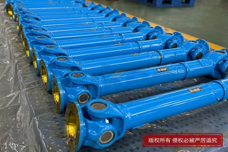
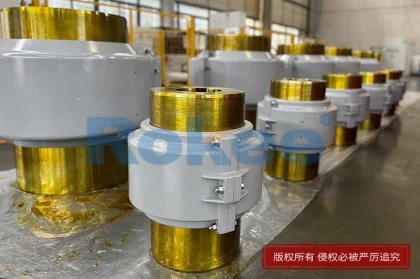
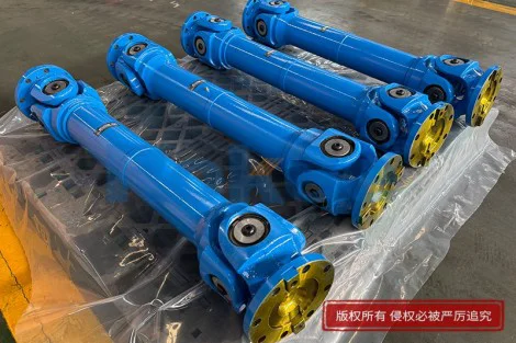
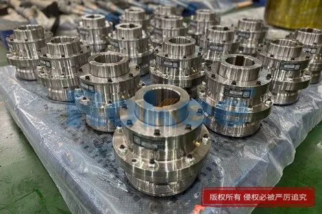
JS Series Grid Coupling
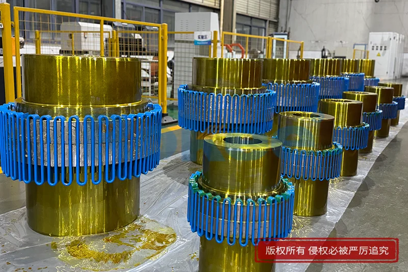
The JS Series grid coupling represents a refined approach to interconnecting distributed energy resources with utility-scale electrical networks, serving as the critical interface where power generation, storage, and load management systems meet the broader grid. At its core, the coupling assembly is engineered to manage the complex interplay between alternating current sources that must remain phase-synchronized, voltage-compatible, and frequency-stable before energy can flow bidirectionally across the boundary. Unlike simple breaker-based connections that merely establish or sever a circuit, the JS Series introduces active control layers that continuously monitor grid conditions and adjust output parameters in real time, ensuring that every watt transferred across the coupling point adheres to the stability requirements of both sides of the interface. This active intervention is particularly valuable in scenarios where the generating side exhibits variability—such as solar arrays whose output fluctuates with cloud cover, or wind turbines whose rotational speed responds to gusting conditions—because the coupling unit can smooth these fluctuations before they propagate into the utility network. The physical construction of the coupling enclosure typically incorporates shielded power electronics modules, insulated busbars, and temperature-managed heat sinks that operate under continuous load, while the control board samples voltage and current waveforms thousands of times per second to detect deviations that would trigger protective disconnection.
The electrical architecture of the JS Series Grid Coupling centers on a set of insulated-gate bipolar transistor bridges that synthesize a sinusoidal output waveform through pulse-width modulation, adjusting the modulation index and phase angle to match the grid's instantaneous voltage vector. This vector control methodology allows the coupling unit to not only transfer active power but also to inject or absorb reactive power independently, providing a degree of voltage support that strengthens the local grid at the point of common coupling. When the grid experiences a voltage sag due to a nearby fault, the control algorithm can increase reactive current injection within milliseconds, a capability known as low-voltage ride-through, which prevents the coupling unit from disconnecting prematurely and thereby avoids cascading tripping events that could destabilize an already compromised network. Conversely, if the grid voltage rises above nominal levels due to reverse power flow from heavily distributed generation, the unit can absorb reactive power to pull the voltage back within acceptable operating bands. The communication layer within the coupling controller supports standardized protocol exchanges with upstream energy management systems, allowing operators to dispatch active and reactive power setpoints dynamically based on market signals, forecasted generation, or grid congestion indicators.
Protection philosophy embedded within the JS series grid coupling is layered and hierarchical, beginning with instantaneous overcurrent protection that trips within microseconds in the event of a semiconductor short circuit or output cable fault. Above this hardware-level protection sits a set of time-delayed overcurrent and earth-fault elements that coordinate with upstream distribution protection devices, ensuring that faults are cleared by the nearest protective device rather than causing unnecessary disconnection of the entire coupling installation. Anti-islanding detection receives particular attention, combining passive methods that monitor voltage magnitude, frequency deviation, and phase jump with active methods that inject small perturbations and measure the system's response. This multi-method approach ensures that even when the local generation and load balance closely match—creating a condition where passive methods might fail to detect islanding—the active perturbation will push the voltage or frequency outside acceptable bands within the required detection window, forcing the coupling unit to disconnect and preventing energization of a de-energized line that could endanger maintenance personnel. The protection settings are configurable through a local human-machine interface or via remote commissioning software, allowing field engineers to adapt thresholds and time delays to the specific characteristics of each installation without requiring hardware changes.
Thermal management within the JS Series coupling assembly is designed for continuous operation across a wide ambient temperature range, relying on forced-air cooling with filtered intake paths that direct airflow across the heat sinks attached to the power semiconductor modules. Internal temperature sensors placed at critical junctions—the heatsink base, the transformer winding, and the control board—feed data to the cooling controller, which modulates fan speed to maintain optimal operating temperatures while minimizing acoustic noise and fan wear. In installations where ambient conditions include high humidity or corrosive atmosphere, the enclosure can be specified with conformal-coated circuit boards and desiccant breathers that prevent condensation inside the cabinet during temperature cycling. The power stage includes DC-link capacitors whose ripple current rating is sized for the worst-case harmonic spectrum expected at rated load, and these capacitors are monitored for temperature and estimated remaining life, providing early warning before degradation leads to unexpected failure. The busbar system connecting the DC link to the semiconductor modules is designed with laminated construction to minimize stray inductance, reducing voltage spikes during switching transients and thereby lowering electrical stress on the devices and extending their operational life.
Monitoring and diagnostic capabilities in the JS Series Grid Coupling extend well beyond basic metering, capturing a comprehensive dataset that includes waveform snapshots of voltage and current at the point of common coupling, harmonic distortion values up to the fiftieth harmonic, power factor measurements, and event logs that record every protective operation with timestamped values of the electrical parameters at the moment of tripping. This data is accessible locally through the display panel and can be streamed remotely using encrypted communication channels, allowing service teams to perform condition-based maintenance rather than relying on fixed inspection intervals. The event recording functionality captures pre-fault and post-fault waveform buffers, giving engineers visibility into the transient behavior that preceded a trip and enabling root-cause analysis that would be impossible with simple status indicators. Diagnostic routines run automatically during startup, performing self-tests on the communication ports, verifying sensor calibration, and checking the integrity of firmware and protection settings before closing the main contactor to connect to the grid. Runtime counters track hours of operation, number of switching cycles, and cumulative energy transferred, providing the data needed for lifecycle management and warranty tracking.
Installation and commissioning procedures for the JS Series have been streamlined through a modular design that separates power cabinet, control cabinet, and interface panel into distinct sections that can be shipped separately and assembled on site. The power terminals are arranged with clear phase identification and generous spacing for cable lugs, reducing wiring errors during installation, and the control section uses pluggable terminal blocks that allow pre-wiring of field cables before connection to the main controller. Commissioning follows a structured sequence: first, the operator enters site-specific parameters such as grid nominal voltage, frequency range, and transformer impedance values; second, the controller performs an open-loop test to verify that voltage and current sensors read correctly; third, a synchronization check confirms that the coupling unit's output frequency and phase align with the grid before the main contactor closes; and finally, a gradual power ramp test verifies that active and reactive power control responds correctly to setpoint changes. The commissioning software guides the technician through each step, flagging inconsistencies and providing pass or fail results for each test, and produces a commissioning report that documents all settings and test outcomes for the installation file. This structured approach reduces the risk of configuration errors that could lead to nuisance tripping or, in the worst case, unsafe operating conditions.
Grid support functions within the JS Series continue to evolve as distribution grids accommodate increasing shares of inverter-based resources. Frequency-watt control allows the coupling unit to reduce active power output as grid frequency rises above nominal, counteracting the excess generation that contributes to high-frequency conditions. Frequency-power control can also respond to under-frequency events by curtailing output or, where the installation includes storage, injecting stored energy to support frequency recovery. Voltage-watt and voltage-var characteristics allow the unit to adjust reactive power output based on local voltage measurements, flattening voltage profiles along feeders that experience significant voltage rise from distributed generation. Ramp-rate limiting controls the rate at which active power changes, smoothing the effect of cloud transients on solar installations and preventing rapid power fluctuations that could challenge grid regulation. Fixed power factor operation allows the unit to maintain a specified power factor regardless of active power output, useful in installations where the utility has specified a power factor requirement. All of these functions can be enabled, disabled, or reparameterized remotely, allowing the coupling unit's behavior to adapt as grid codes evolve or as the characteristics of the local distribution network change over time.
The mechanical and enclosure design of the JS Series Grid Coupling prioritizes both serviceability and environmental protection. The main cabinet is constructed from folded sheet steel with a corrosion-resistant coating, and the front door carries gasketing that maintains an appropriate ingress protection rating against dust and water jets. Internal cable management separates power and signal cables into dedicated trunking runs, minimizing electromagnetic interference that could affect the sensitive control circuits. The main contactor or circuit breaker that physically connects the power electronics output to the grid is located in an accessible compartment with clear isolation gaps, and emergency stop buttons are positioned on the front panel and, optionally, at remote locations to allow rapid disconnection during maintenance or emergency situations. Grounding provisions include an external earth stud for the protective earth conductor and internal bonding points that connect the cabinet frame, cable trays, and shielded cable braids to the grounding system. The layout of internal components follows a thermal gradient principle, placing heat-generating components in the airflow path and heat-sensitive control electronics away from hot surfaces, while maintaining sufficient clearance for service personnel to work on live circuits with appropriate lockout-tagout procedures.
Cybersecurity considerations for the communication interfaces of the JS Series have been incorporated at both the device and network layers. The controller supports role-based access control, distinguishing between viewing-only users, commissioning engineers, and administrative users, with credentials that can be rotated and audited. Communication sessions with remote monitoring platforms use encrypted transport protocols, and firmware updates are signed to prevent unauthorized code from being loaded onto the controller. The device maintains an audit log that records configuration changes, access events, and protective operations, providing a forensic trail that can be reviewed during security assessments or post-incident investigations. Network ports that are not in use can be physically or logically disabled, reducing the attack surface, and the device supports network segmentation best practices by operating on a dedicated management network that is isolated from the operational power circuit. Time synchronization through network time protocols ensures that event timestamps from multiple devices across a site are aligned, making it possible to correlate events across the installation when diagnosing complex system behavior. These security measures are designed to align with the expectation that grid-connected equipment will be a target for both accidental misconfiguration and deliberate attack, and they provide operators with tools to maintain the integrity of the coupling installation over its operational lifetime.
The overall value proposition of the JS Series Grid Coupling lies in its ability to transform a relatively raw energy source—whether from photovoltaic arrays, wind turbines, battery storage systems, or combined heat and power units—into grid-compliant power that can be confidently accepted by the distribution network. By handling synchronization, power quality management, protection, and grid support functions within a single integrated assembly, the coupling reduces the engineering complexity that would otherwise be distributed across multiple discrete components, each requiring separate configuration and coordination. The result is a system that adapts to changing grid conditions, provides diagnostic visibility into its own operation, and supports the ongoing transition toward distributed, renewable-rich power systems. As grids around the world continue to evolve, the requirements placed on grid coupling equipment will likewise evolve, demanding faster response times, richer grid support functions, and deeper integration with distribution management systems. The modular architecture of the JS Series positions it to accommodate these future requirements through firmware updates and optional function modules, extending its useful life and protecting the operator's investment over decades of operation. In this way, the grid coupling assembly serves not merely as a passive connection point but as an active, intelligent participant in the ongoing management of the electrical network.