Heavy Duty Grid Coupling
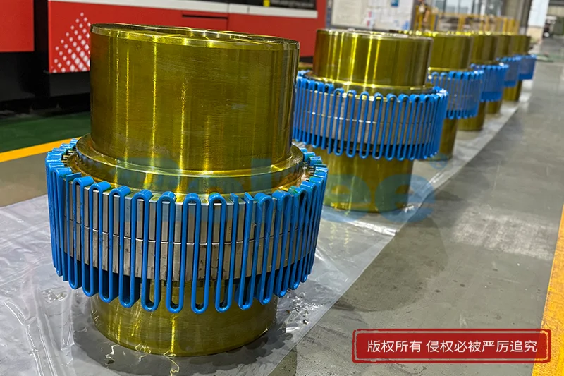
In the world of industrial machinery, where rotating shafts must transfer torque between prime movers and driven equipment with unwavering reliability, the heavy duty grid coupling stands as one of the most trusted and versatile mechanical connection solutions available. Unlike rigid couplings that demand perfect shaft alignment or elastomeric designs that degrade under extreme loads, a heavy duty grid coupling bridges the gap between flexibility and strength by employing a distinctive metallic spring element—a grid—sandwiched between two mating hubs. This interlocking grid transmits torque while simultaneously accommodating angular, parallel, and axial misalignment, absorbing shock loads and damping vibration that would otherwise propagate through the entire drivetrain. The coupling's ability to perform consistently under heavy, fluctuating, or impactive loads makes it indispensable in industries where downtime is measured in thousands of dollars per hour and mechanical failure carries severe safety consequences.
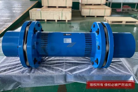
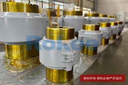
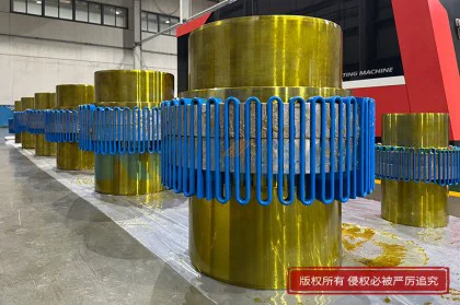
The fundamental architecture of a heavy duty grid coupling begins with two precisely machined hubs, typically crafted from high-strength alloy steel or ductile iron, each featuring a series of curved or straight tooth-like slots along their outer circumference. The grid element itself is a flat, spring-steel strip wound in a serpentine or zigzag pattern that nests into the teeth of both hubs simultaneously. As torque passes from one hub to the other, it is distributed across the entire length of the grid rather than concentrated at a single point, creating a load-spreading effect that enhances both torque capacity and fatigue resistance. The outer periphery of the coupling is enclosed by a split or one-piece cover, usually cast from aluminum or steel, which retains a reservoir of lubricating grease or oil. This lubrication is critical: it reduces friction between the moving grid and hub teeth, dissipates heat generated during misalignment compensation, and extends the service life of all contacting surfaces. The cover also serves as a safety shield, preventing operator contact with moving components and containing any grease expelled under centrifugal force.
The working principle behind a heavy duty grid coupling combines the mechanical advantage of a spring with the kinematic freedom of a universal joint, albeit in a purely metallic form. When the driving hub rotates, its teeth press against the grid, which in turn pushes against the driven hub's teeth, transmitting rotational energy across the interface. Because the grid is not rigidly bolted to either hub—it merely rests within the tooth grooves—it can flex and slide slightly as the shafts rotate. This micro-motion is what enables misalignment compensation: angular misalignment is absorbed as the grid twists within the tooth gaps, parallel offset is handled by the grid's lateral deflection, and axial movement is accommodated by the grid sliding along the hub teeth. The spring rate of the grid is deliberately engineered to provide just enough flexibility to dampen shock and vibration without introducing excessive torsional windup, which could impair positioning accuracy or introduce torsional resonance at critical operating speeds. This balance is precisely what has made grid couplings a preferred choice for heavy, pulsating, or reversing drives.
The range of applications for heavy duty grid couplings spans virtually every sector of heavy industry. In mining operations, they connect electric motors to crushers, mills, conveyors, and excavators, where ore impact and sudden load spikes would destroy less robust coupling designs. In steel mills, they endure the heat, dust, and continual rolling-mill torque reversals that punish rubber elements and fragile diaphragm couplings alike. Pulp and paper mills rely on them for refiners, chest agitators, and dryer section drives, where long shaft spans and thermal expansion create substantial misalignment challenges. Power generation plants use them for boiler feed pumps, cooling tower fans, induced draft fans, and auxiliary turbine drives, often in high-temperature environments where polymer components would quickly embrittle. Marine propulsion, offshore drilling, quarrying, cement processing, and heavy manufacturing all draw on the same core technology. The coupling's tolerance for sustained heavy load combined with its misalignment-handling capability makes it the default choice whenever an engineer specifies a drive that must run for years between overhauls.
One of the most significant advantages of a heavy duty grid coupling is its inherent vibration-damping behavior. When a driven machine experiences a sudden load surge—a jaw crusher encountering a boulder, a conveyor chain snatching under start-up, a reciprocating compressor pulsing on each stroke—the grid flexes rather than transmitting the impulse directly to the motor. This spring action absorbs the energy spike and releases it gradually, protecting motor windings, gearbox bearings, shaft keyways, and foundation bolts from repeated shock fatigue. Field studies and lab measurements consistently show that properly lubricated grid couplings can reduce peak torque transients by a substantial margin compared to rigid or jaw-type couplings, which is why they are specified on every new installation involving diesel-engine-driven equipment, hammer mills, reciprocating pumps, and reversing rolling mills. The damping effect also reduces audible noise from the drive train, improving workplace conditions and cutting down on the stress that chronic vibration imposes on surrounding structure.
Misalignment tolerance is another hallmark benefit. Even with the most careful laser alignment during installation, thermal growth, foundation settlement, bearing wear, and pipeline strain will gradually introduce misalignment between connected shafts. A heavy duty grid coupling is designed from the outset to accept reasonable angular, parallel, and axial offsets without imposing harmful side loads on bearings. The grid's sliding action converts what would otherwise be a destructive binding force into a controlled, lubricated movement. This tolerance not only extends bearing and seal life on both machines but also relaxes the precision demanded during initial installation, reducing installation labor and the need for repeated realignment during routine maintenance. Engineers often specify grid couplings precisely when shaft separation is large, equipment is mounted on independent structures, or operating temperatures vary widely—scenarios where perfect alignment is physically unattainable over the equipment's lifetime.
Material selection and heat treatment underpin the durability of every heavy duty grid coupling. Hubs are commonly forged from medium-carbon or alloy steels, then normalized or quenched and tempered to achieve a balance of tensile strength, toughness, and machinability. The grid itself is a precision-rolled spring steel, typically through-hardened and shot-peened to introduce compressive residual stresses that resist fatigue crack initiation. Tooth profiles are designed to minimize stress concentration, with polished radii at groove roots where fatigue failures would otherwise begin. Covers are often cast aluminum to keep rotating mass low and reduce windage, though cast or fabricated steel covers are used in high-temperature or abrasive environments. The lubricant is not an afterthought: specialized extreme-pressure grease with high film strength is formulated to remain in the tooth grooves under centrifugal force, resist washout by water or process fluids, and provide corrosion protection during prolonged shutdowns. Together, these material choices allow a well-maintained grid coupling to operate for a decade or more under continuous heavy duty service.
Proper installation and maintenance practices are essential to realizing the full service life of a heavy duty grid coupling. During installation, shafts are first aligned to the manufacturer's recommended cold offset, accounting for thermal growth that will occur at operating temperature. Hubs are typically mounted with interference or shrink fits, secured by keyways, set screws, or taper-lock bushings depending on torque density. The grid is then inserted into the hub teeth by hand, taking care not to roll or kink the spring strip, and the cover is fitted and bolted to the specified torque. After initial run-in, the coupling should be re-greased and inspected; thereafter, relubrication intervals are established based on operating hours, ambient temperature, and severity of service. Routine maintenance includes checking cover seal integrity, listening for unusual clicking or grinding from the tooth interface, verifying shaft alignment at scheduled intervals, and inspecting the grid for cracking or permanent deformation whenever the cover is removed. A grid that has fatigued to the point of fracture rarely fails without warning, and periodic inspection catches the vast majority of deteriorations long before catastrophic separation occurs.
When problems do arise with heavy duty grid couplings, they generally trace back to a handful of root causes. Premature grid fracture usually indicates either excessive misalignment beyond the coupling's rated capacity, insufficient lubrication causing metal-to-metal wear, or operation at a torsional resonant speed that has introduced cyclic fatigue. Hub tooth wear appears as polishing, pitting, or grooving along the contact flanks and points to lubricant breakdown, contamination, or sustained overload. Cover seal leaks lead to grease loss and accelerated wear, and should be addressed before the grid runs dry. External symptoms such as high bearing temperatures on adjacent machines, abnormal vibration spectra with dominant frequencies at shaft speed, or visible coupling noise during start-up all signal that an inspection is overdue. Troubleshooting follows a disciplined path: verify alignment first, confirm lubricant condition and level, inspect tooth and grid condition, review the application duty cycle against the coupling's torque and speed rating, and check for soft-foot or foundation issues that may be forcing misalignment on the connected equipment. Addressing these systemic issues rather than simply replacing the grid is the key to long-term reliability.
Looking ahead, the heavy duty grid coupling continues to evolve in response to the demands of modern industrial drives. Computational optimization of tooth profiles using finite element analysis has allowed manufacturers to push torque density higher while keeping inertia low. Surface coatings, improved metallurgy, and advanced grease formulations have extended relubrication intervals and expanded the temperature operating envelope. Smart condition monitoring—vibration sensors, acoustic emitters, and even embedded wear indicators within the cover—are increasingly integrated into large-scale installations, allowing maintenance teams to predict grid fatigue before failure. Yet for all these advances, the fundamental design remains remarkably unchanged: a flexible metallic grid between two toothed hubs, enclosed in a lubricated cover, absorbing shock, tolerating misalignment, and transmitting torque with a quiet, dependable efficiency that has earned its place on factory floors for generations. In an era of increasingly sophisticated servo and digital drive systems, the humble heavy duty grid coupling endures because it solves a mechanical problem with mechanical elegance, and that combination remains as relevant in the modern plant as it was when the first grid strip was wound between two hubs over a century ago.