Grid Flexible Shaft Coupling
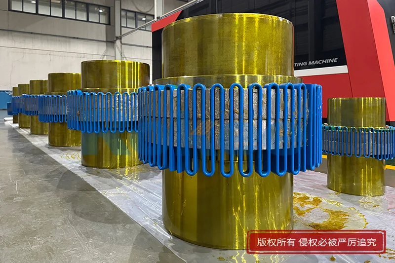
A grid flexible shaft coupling is a mechanical device designed to connect two rotating shafts in a power transmission system while accommodating misalignment and damping vibration. At its core, this type of coupling relies on a slender, spring-like metallic grid that bridges the gap between two hubs, each fitted with precision-machined teeth or slots. The grid itself is typically made from high-strength steel and shaped into a serpentine or zigzag form, allowing it to flex under load without permanent deformation. Unlike rigid couplings that demand perfect shaft alignment, grid couplings permit small angular, parallel, and axial deviations between the connected shafts, which is essential in real-world machinery where perfect alignment is rarely achievable. This flexibility is not merely a convenience; it protects bearings, seals, gears, and other connected components from premature wear caused by misalignment-induced forces. The coupling also serves as a flexible torque transmitter, transferring rotational power from a driving unit such as an electric motor or engine to a driven unit such as a pump, compressor, conveyor, or gearbox. The design balances strength, flexibility, and damping capability in a way that has made it a popular choice across a broad spectrum of industrial applications.
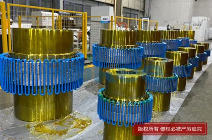
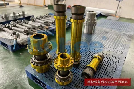
The construction of a grid flexible shaft coupling typically comprises two hubs and a grid spring, often enclosed within a protective cover. The hubs are usually manufactured from cast iron, steel, or sometimes ductile iron, depending on the torque rating and environmental conditions. Each hub features a series of precisely cut teeth around its outer circumference, with the teeth on the driving and driven hubs facing each other across the gap. The metallic grid nests into these tooth gaps, forming a continuous load path from one hub to the other. The grid is not a flat strip but is curved along its length, resembling a long, wavy spring. This curvature gives the grid its ability to bend and twist under misalignment. The cover, often made from stamped sheet metal or cast aluminum, surrounds the grid to retain lubricant and prevent personnel contact with moving parts. Some designs include a split cover for easy grid inspection and replacement without moving the connected machinery. The hubs may be bored to specific shaft diameters or supplied with keyless locking devices for secure, backlash-free mounting. The overall assembly is compact, with a short overall length relative to the torque it can transmit, making it suitable for space-constrained equipment installations.
The operating principle of a grid flexible shaft coupling hinges on the elastic deformation of the metallic grid as it transmits torque. When the driving hub rotates, its teeth press against the grid, which in turn pushes against the teeth of the driven hub. Because the grid is a continuous spring-like element, it distributes the load across multiple teeth rather than concentrating it on a single point. This distributed loading improves the coupling's torque capacity and smooths out torque fluctuations. When misalignment exists between the two shafts, the grid flexes within the tooth gaps, bending in response to angular or parallel offset. The amount of flex is limited by the clearance between the grid and the tooth flanks, as well as by the grid's own material properties. Axial movement of the shafts is accommodated by the grid sliding slightly within the tooth gaps along the shaft direction. The flexing action of the grid also introduces a damping effect: as the grid bends and relaxes repeatedly, friction between the grid and the tooth surfaces, combined with the hysteresis of the steel spring, absorbs and dissipates vibrational energy. This damping characteristic is particularly valuable in systems subjected to shock loads, cyclic torque variations, or torsional vibration, as it reduces resonant peaks and protects the drivetrain from fatigue failure.
Grid flexible shaft couplings are available in several configurations tailored to different installation and performance requirements. The most common form is the horizontally split cover design, where the cover halves can be removed radially to expose the grid for inspection or replacement without disturbing the shaft alignment or moving the connected equipment. Another variation is the vertically split cover, which opens along a plane perpendicular to the shaft axis, useful in installations where radial access is limited. Some couplings are offered without a cover at all, typically for clean, well-lubricated, and non-critical applications where personnel safety permits open operation. Grid profiles also vary: some use a curved grid with a uniform cross-section, while others employ a tapered or stepped grid to tune stiffness and flexibility. Bushed or flanged versions extend the coupling's versatility, allowing it to mate to standard motor or gearbox shaft flanges. Certain heavy-duty designs incorporate reinforced hubs or higher-strength grid materials for demanding applications such as mining equipment, steel mill drives, and large fans. The choice of configuration depends on factors such as accessible space, service frequency, environmental contamination, and the level of protection required for operating personnel.
The range of applications for grid flexible shaft couplings spans virtually every industry that relies on rotating machinery. In the pump and compressor sector, these couplings connect electric motors to centrifugal pumps, reciprocating compressors, and blowers, where misalignment compensation and vibration damping protect mechanical seals and bearings. In material handling, they drive conveyors, bucket elevators, and crushers, often under conditions of shock load and dust. The power generation industry uses them in turbine-driven auxiliaries, generator sets, and cooling tower fans, where reliable torque transmission over long periods is critical. Steel and aluminum mills employ them on roller table drives, descaling pumps, and main gearbox inputs, where heavy loads and harsh environments demand robust coupling construction. Mining operations use them on slurry pumps, mill drives, and screening equipment, often in remote and abrasive settings. Food and beverage processing relies on smaller grid couplings for mixers, packaging lines, and refrigeration compressors, where smooth operation prevents product damage. Marine applications use them on auxiliary engine drives and thrusters. The common thread across these industries is the need for a coupling that can transmit substantial torque while tolerating inevitable shaft misalignment and absorbing the vibrational energy that would otherwise accelerate component failure.
One of the primary advantages of grid flexible shaft couplings is their inherent ability to damp torsional vibration. Unlike elastomeric couplings, which rely on rubber or polyurethane elements that degrade with age and temperature, the metallic grid provides consistent damping throughout its service life. This damping effect reduces resonant amplitudes in the drivetrain, extending the fatigue life of shafts, keys, bearings, and gears. Another advantage is the coupling's high torque density: because the metallic grid is both strong and flexible, the coupling can transmit more torque in a smaller envelope than many other coupling types. The grid also compensates for all three types of misalignment simultaneously—angular, parallel, and axial—within specified limits, reducing the need for perfect alignment during installation. The coupling's wear surfaces are confined to the grid and tooth contacts, which are lubricated and easily replaceable, making maintenance economical. Hubs typically outlast the grid by many service intervals, so only the grid element needs periodic replacement. Grid couplings also tolerate moderate temperature extremes better than elastomeric alternatives, as steel does not soften or become brittle within the temperature ranges encountered in most industrial settings. These characteristics combine to make grid couplings a cost-effective, long-lasting solution for demanding power transmission applications.
Proper installation is critical to realizing the full performance and service life of a grid flexible shaft coupling. Before installation, the shaft ends must be checked for cleanliness, proper diameter, and appropriate keyway fit. The hubs are typically heated or pressed onto the shafts, with care taken not to exceed the allowable interference fit. Once both hubs are mounted and the shafts are positioned at the manufacturer-recommended gap, alignment must be performed using dial indicators or laser alignment tools. While the coupling tolerates misalignment, excessive misalignment accelerates grid fatigue and increases reactive forces on bearings. The grid is then seated into the tooth gaps, taking care that it lies flat and fully engages the teeth on both hubs. The cover halves are installed, and the specified lubricant—a high-viscosity grease or oil designed for grid coupling service—is introduced through the cover's grease fitting. Over-greasing should be avoided, as it can cause overheating and seal failure; under-greasing leads to rapid wear. The coupling guard must be securely fastened before equipment startup. During initial operation, the coupling should be monitored for unusual noise, heat, or vibration, which may indicate improper seating, insufficient lubrication, or residual misalignment. Following installation, a re-alignment check after the first few hundred hours of operation is recommended, as shafts and foundations may settle or shift under thermal expansion and load.
Routine maintenance of a grid flexible shaft coupling is straightforward but essential for long-term reliability. The primary maintenance task is periodic lubrication, with intervals depending on operating speed, load, temperature, and environment. The cover should be inspected for grease leakage, cracked housing, or missing fasteners at regular intervals. The grid itself should be inspected during scheduled shutdowns by removing the cover halves, looking for cracks, permanent deformation, or excessive wear on the grid edges and tooth surfaces. Worn grids show signs of fretting corrosion, pitting, or elongation at the contact points. If any of these conditions are observed, the grid should be replaced before it fails catastrophically. Replacement grids are matched to the specific coupling size and style, and installation should follow the same procedure as initial assembly. Reusing a worn grid is not recommended, as fatigue damage is progressive and may not be visible to the naked eye. Hubs should be checked for tooth wear, hub bore damage, and corrosion, especially in washdown or outdoor environments. Keyless locking devices should be re-torqued according to their maintenance schedule. Maintaining a simple maintenance log that records lubrication dates, inspection findings, and component replacements helps predict remaining service life and avoids unplanned downtime.
Understanding common failure modes helps operators diagnose and prevent grid coupling problems. The most frequent failure cause is grid fracture due to fatigue, typically triggered by excessive misalignment, inadequate lubrication, or operation beyond the coupling's torque rating. Fatigue cracks usually initiate at the grid's stress concentration points, such as bends or transitions in cross-section, and propagate until the grid snaps. Another common issue is fretting corrosion between the grid and tooth surfaces, caused by microscopic relative motion in the presence of air and insufficient lubricant. Fretting appears as reddish-brown oxide deposits and can lead to accelerated wear and eventual grid breakage. Tooth wear on the hubs, visible as polishing or deformation on the tooth flanks, occurs when the grid is inadequately lubricated or when misalignment forces the grid to rock excessively. Cover failure, such as cracked housing or loose fasteners, can result from prolonged vibration or impact and creates a safety hazard. Overheating, indicated by discolored grid material or burnt grease smell, usually points to over-greasing, excessive speed, or high ambient temperature. Shaft key shear or hub bore damage may occur if the coupling was sized too small for the application or if shock loads exceeded the design margin. Proper troubleshooting begins with inspecting the grid and teeth, verifying alignment, confirming lubrication quality and quantity, and reviewing operating conditions against the coupling's rated capacity.
Selecting the right grid flexible shaft coupling involves matching the coupling's torque capacity, bore range, and envelope dimensions to the specific application. The process begins with determining the required design torque, which combines the nominal torque of the driven equipment with a service factor that accounts for shock loads, frequent starts, and environmental severity. The coupling must also be able to accommodate the maximum expected misalignment, both at installation and during thermal expansion of the shafts. Bore sizes must fit both the driving and driven shafts, and the coupling's overall length must fit within the available shaft gap. Operating speed is another critical parameter, as high speeds introduce centrifugal forces that can affect the grid and require a balanced or dynamically trimmed coupling. Environmental conditions such as temperature, moisture, dust, and chemical exposure influence the choice of hub material, cover design, and lubricant type. Looking forward, trends in coupling design include the use of advanced surface treatments and coatings to extend grid fatigue life, the integration of condition monitoring sensors into the cover to detect wear and vibration remotely, and the exploration of new grid materials and geometries to improve damping while reducing weight. Digital tools now allow engineers to model the torsional dynamics of the entire drivetrain, including the coupling, before making a selection, optimizing the balance between flexibility, stiffness, and damping. As industrial machinery becomes more efficient and demands higher reliability, the grid flexible shaft coupling continues to evolve, yet its fundamental principle—a flexible metallic grid that transmits torque while accommodating misalignment—remains as relevant today as when it was first introduced.