Snake Spring Flexible Coupling
A snake spring flexible coupling is a mechanical device designed to connect two rotating shafts in a power transmission system while accommodating misalignment and dampening torsional vibration. At its core, this type of coupling relies on a curved, serpentine-shaped metallic spring that sits between radial teeth or pockets on two opposing hubs. As torque travels from the driving shaft to the driven shaft, the spring flexes and distributes the load across multiple contact points rather than concentrating stress at a single rigid junction. This fundamental design philosophy distinguishes it from rigid couplings, which demand near-perfect shaft alignment and transmit shock loads directly, and from elastomeric couplings, which rely on rubber or polyurethane elements that degrade under sustained high-temperature or high-torque conditions. The snake spring coupling occupies a practical middle ground: it handles substantial torque loads while absorbing the inevitable misalignments and dynamic shocks that arise in real-world machinery. Because the flexing element is made of steel rather than a polymer, the coupling maintains its performance characteristics across a wide temperature range and is less susceptible to fatigue from prolonged torsional cycling. Engineers often specify this type of coupling in drivetrains where reliability is paramount and where downtime would carry significant operational or financial consequences. The coupling's ability to transmit torque through a series of distributed tooth contacts also means that if one tooth were to experience localized overload, the neighboring teeth and the spring itself would continue to carry a portion of the load, providing a degree of fail-safe behavior that rigid couplings cannot match. This characteristic has made snake spring couplings a trusted choice in critical rotating equipment for many decades.
The development of the snake spring flexible coupling traces back to early twentieth-century engineering efforts to solve the persistent problem of shaft misalignment in industrial machinery. Before such flexible elements were widely adopted, engineers relied on rigid couplings, chain couplings, or gear-type couplings that required meticulous alignment and suffered from rapid wear under dynamic loading conditions. The introduction of a curved steel grid spring engaged with radial hub teeth represented a significant leap forward, because it combined the high torque density of a metallic power path with the compliance needed to tolerate angular, parallel, and axial misalignment. Over the decades, refinements in tooth profile geometry, spring cross-sectional shaping, and hub material selection have progressively improved the coupling's torque capacity, misalignment tolerance, and service life. Manufacturers experimented with different spring curvature radii, contact angles, and lubrication channel configurations to optimize both vibration damping and efficiency. The design also benefited from advances in metallurgy that allowed the spring to be manufactured from high-strength, fatigue-resistant steels capable of enduring billions of flex cycles without permanent deformation. As industrial drivetrains became more powerful and operating speeds increased, the snake spring coupling evolved in parallel, with larger frame sizes and specialized tooth profiles developed for high-speed turbomachinery and heavy-duty rolling mills. Despite the proliferation of alternative flexible coupling technologies in later years—including disk couplings, diaphragm couplings, and jaw-type elastomeric designs—the snake spring coupling has retained a loyal following in applications where its unique combination of torque density, misalignment tolerance, and dampening capability is valued. Its long history of successful service in the field has produced a body of practical knowledge about installation practices, lubrication regimens, and failure analysis that continues to guide engineers today.
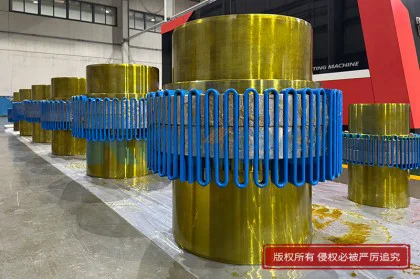
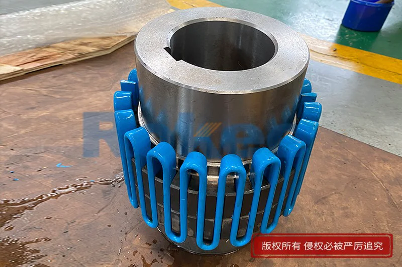
The mechanical construction of a snake spring flexible coupling consists of several key elements that work in concert to transmit torque while allowing relative shaft movement. The two main components are the driving hub and the driven hub, each machined with a series of evenly spaced radial teeth or pockets on their facing surfaces. The teeth on opposing hubs are offset so that the serpentine spring weaves between them, engaging with one tooth on the driver side and the adjacent tooth on the driven side as it winds around the circumference. This interlocking arrangement creates a continuous load path from the input shaft to the output shaft through the spring itself. The spring is typically a flat steel strip that has been bent into a wave-like or snake-like shape along its length, and it sits in the annular space between the two hub halves. An outer cover or guard surrounds the coupling to retain lubricant and provide a safety barrier. The cover is usually split axially for easy removal without disturbing the connected shafts, and it contains seals at the points where the hubs emerge to prevent grease leakage and exclude contaminants. Behind the hubs, keyways or interference fits secure each hub to its respective shaft, and in some designs, clamping devices or taper bushings provide additional retention. The tooth profile on the hubs is carefully shaped so that the spring can slide and flex along the tooth flank as the shafts rotate and misalignment occurs. The contact surfaces between the spring and the teeth are often case-hardened or treated to resist pitting and wear, since these are the primary friction and load-bearing interfaces. The overall assembly is compact in the axial direction compared to many other flexible coupling types, which makes it suitable for installations where space is constrained along the shaft line.
The snake spring itself is the defining component of this coupling type, and its design and material properties largely determine the coupling's performance envelope. Typically manufactured from a high-carbon or alloy steel strip, the spring is heat-treated to achieve a balance of hardness and toughness that allows it to flex repeatedly without fatigue cracking. The cross-section of the spring is often rectangular, with the wider dimension oriented in the direction of torque transmission to maximize load-bearing capacity while preserving flexibility in the bending direction. The serpentine curvature—formed by bending the strip into a series of waves along its length—creates the spring-like behavior that enables the coupling to accommodate misalignment and absorb shock. As torque is applied, the spring compresses against the tooth flanks on the driving side and simultaneously pushes against the opposing teeth on the driven side, transferring rotational force through the contact pressure. The flexing of the spring along its curved length acts as a torsional spring, introducing a degree of compliance into the drivetrain. This compliance shifts the natural torsional frequency of the system away from critical operating speeds and dissipates vibrational energy through friction between the spring and the hub teeth, as well as through internal hysteresis within the steel itself. The spring's curvature radius, wave amplitude, and number of waves per revolution are all engineering variables that can be tuned to achieve a desired torsional stiffness for a specific application. A stiffer spring profile offers higher torque capacity but less dampening, while a more flexible profile provides greater vibration absorption at the cost of lower torque density. The spring is also designed to be easily replaceable, allowing maintenance personnel to swap out a worn spring without replacing the entire coupling, which reduces long-term operating costs. In larger couplings, multiple spring segments may be joined end-to-end to form a complete ring, and the ends are typically welded or hooked together to prevent separation during operation.
Torque transmission in a snake spring flexible coupling occurs through a distributed contact mechanism that distinguishes it from single-point or few-point torque paths. When the driving hub rotates, its radial teeth push against the serpentine spring at multiple points around the circumference. The spring, in turn, transmits this force to the teeth of the driven hub, causing the driven shaft to rotate in unison. Because the spring contacts many teeth simultaneously—often a dozen or more depending on coupling size and design—the load is shared across a broad arc rather than concentrated on a single key or spline. This load distribution dramatically reduces contact stress at any one point and is one reason these couplings can transmit high torque in a relatively compact envelope. The flexible nature of the spring also allows it to absorb torsional shocks that occur when the driven load experiences sudden changes, such as the startup of a heavy crusher, the reversal of a rolling mill, or the impact load from a reciprocating compressor. Instead of the shock traveling rigidly back to the prime mover, the spring deforms and stores a portion of the energy as elastic strain, then releases it gradually as the system catches up. This dampening effect protects both the driving equipment and the driven equipment from premature fatigue failure. Misalignment accommodation works through the same flexing mechanism: angular misalignment causes the spring to bend slightly differently on one side of the coupling versus the other, parallel offset causes a lateral shift in the spring's position between the teeth, and axial movement allows the spring to ride slightly along the tooth direction. The coupling tolerates these deviations continuously during operation without generating the large reaction forces that rigid couplings impose on bearings. The trade-off is that the sliding contact between the spring and the hub teeth creates friction, which necessitates proper lubrication and generates a small amount of heat under high-misalignment or high-torque conditions.
Installing a snake spring flexible coupling requires careful attention to shaft alignment, even though the coupling itself is designed to tolerate some misalignment. The coupling's misalignment capacity is not unlimited, and operating beyond its design tolerance accelerates wear on the spring and hub teeth, reduces service life, and introduces additional loads into the connected machinery's bearings. The installation process begins with mounting the two hubs onto their respective shafts, typically using keyed interference fits or taper-lock bushings that provide concentricity and torque retention. Once the hubs are seated, the shafts are brought into approximate alignment, and the serpentine spring is installed by weaving it between the opposing radial teeth. The cover is then placed over the assembly and secured with fasteners, after which lubricant is introduced through a fitting. Precision alignment is then performed using dial indicators, laser alignment tools, or alignment brackets that measure both angular and parallel offset at the coupling face. The goal is to bring the shafts well within the coupling's rated misalignment tolerance—often to a fraction of the coupling's maximum allowable value—so that the coupling operates in its central, most comfortable range. Thermal growth must also be considered: if one machine operates at a significantly higher temperature than the other, its shaft will expand axially and potentially shift vertically, and the cold alignment must be set to compensate for this predicted movement. Axial float clearance must be verified so that the coupling does not bind when shafts expand during operation. The spring should be inspected during installation to ensure it is properly seated in all tooth pockets and that no segment is twisted or caught on a tooth edge. The cover seals should be checked for correct installation to prevent grease loss. Proper installation not only extends coupling life but also protects the connected equipment from unnecessary bearing loads and reduces the risk of premature failure in adjacent components.
Maintenance of a snake spring flexible coupling centers on lubrication management, periodic inspection, and timely replacement of wear components. The coupling relies on a film of grease between the spring and the hub teeth to reduce friction, dissipate heat, and protect the contact surfaces from corrosion and abrasive wear. The recommended lubrication interval depends on operating conditions, but typical practice calls for fresh grease to be introduced at regular intervals while the old grease is expelled through the cover's drain or relief path. Over-greasing can cause excessive churning heat and pressure buildup, while under-greasing leads to metal-to-metal contact and rapid wear of the spring and tooth flanks. The choice of lubricant is also important: a lithium-based or extreme-pressure grease with suitable viscosity for the operating temperature range is generally specified, and oil lubrication may be used in certain high-speed or high-temperature applications. During routine inspections, maintenance personnel check the cover seals for leaks, examine the exterior of the coupling for signs of unusual vibration or heating, and monitor the driven equipment's bearing temperatures as indirect indicators of coupling health. At major overhaul intervals, the cover is removed and the spring is extracted for close examination. The spring should be checked for fatigue cracks, particularly at the points of maximum flexure, and for flattening or wear on its contact edges. The hub teeth are inspected for pitting, scoring, or wear that has altered the tooth profile. If the spring shows significant wear or cracking, it is replaced; if the hub teeth are worn beyond acceptable limits, the hubs themselves may need to be replaced or reconditioned. Because the spring is the only wearing element in the coupling—aside from the seals—its predictable replacement cycle simplifies maintenance planning. Operators often keep spare springs on hand so that a worn coupling can be restored to service quickly during a planned shutdown. The coupling's modular design also means that replacing a spring is far less costly than replacing an entire gear or disk coupling assembly.
Failure modes in snake spring flexible couplings provide valuable diagnostic information about the operating conditions and installation quality of the drivetrain. The most common wear pattern is thinning or flattening of the spring at its contact edges, which occurs gradually over millions of cycles as the spring slides against the hub teeth. When this wear becomes excessive, the spring develops slack in the torque path, leading to noticeable backlash and vibration in the drivetrain. A more serious failure mode is fatigue fracture of the spring, which typically initiates at a surface defect, a corrosion pit, or a sharp bend in the spring where stress concentration is highest. Fatigue cracks often propagate across the spring's width until the remaining cross-section can no longer carry the torque, at which point the spring fractures and may cause sudden loss of power transmission. Such failures are more likely when the coupling is operated at or near its torque limit, when misalignment exceeds design tolerance, or when the spring material has been degraded by overheating. Hub tooth failures manifest as pitting on the tooth flanks, caused by repeated contact stress exceeding the material's fatigue limit, or as abrasive wear from inadequate lubrication. In extreme cases, the teeth can shear off entirely if a torsional overload exceeds the combined strength of the spring and tooth interfaces. Seal failure leads to grease leakage and contamination ingress, which accelerates wear and can cause the coupling to run dry. When a coupling failure occurs, maintenance engineers analyze the wear pattern on the removed components to determine the root cause. Even wear around the spring circumference suggests normal operation, while localized wear on one side points to misalignment or angular offset. Blue or brown discoloration on the spring indicates overheating, possibly from excessive churning friction or sustained operation above the temperature rating. Corrosion on the spring or hub teeth indicates a lubrication or seal failure. This forensic analysis helps correct not only the coupling itself but also the underlying installation or operating condition that caused the failure.
Snake spring flexible couplings find application across a broad spectrum of industrial machinery where torque density, misalignment tolerance, and vibration dampening are simultaneously required. In the pulp and paper industry, these couplings connect the drives of paper machines, refiners, and stock preparation equipment, where constant running, high torque, and moderate misalignment are the norm. In mining and metallurgical plants, they drive crushers, ball mills, conveyor systems, and vibrating screens, absorbing the severe shock loads that characterize mineral processing operations. The steel industry uses them on rolling mill drives, run-out tables, and coilers, where reversing loads and heavy inertia demand a coupling that can withstand repeated torsional cycling. In the power generation sector, they are employed in boiler feed pump drives, induced draft fan drives, and coal pulverizer auxiliaries, where reliability over long continuous running periods is essential. The marine and offshore industries specify them for winch drives, bow thrusters, and auxiliary machinery where space is limited and where the coupling must tolerate vibration and misalignment in a dynamic environment. In chemical and petrochemical plants, they drive pumps, compressors, mixers, and agitators, often in hazardous areas where the coupling's all-metal construction and enclosed cover reduce the risk of ignition. The water and wastewater industry uses them on pump stations and treatment plant equipment, where the coupling must operate reliably with minimal attention in remote locations. Food and pharmaceutical applications, where washdown or sanitary conditions prevail, may use specialized corrosion-resistant variants of the coupling. The oil and gas upstream sector employs them on shale shakers, centrifuges, and mud pump drives, where shock and vibration are constant companions. Across all these sectors, the coupling's ability to operate reliably in harsh environments, its relatively low maintenance requirement, and its fail-safe distributed torque path make it a default choice for drivetrain engineers who prioritize uptime and equipment protection.
Looking toward the future, snake spring flexible couplings continue to evolve in response to broader trends in industrial machinery, even as their fundamental mechanical principle remains unchanged. One direction of development is the use of advanced materials and surface treatments to extend spring fatigue life further. High-performance coatings, improved case-hardening techniques, and refined alloy compositions allow springs to endure more cycles and operate at higher torque densities within the same envelope. Another trend is the integration of condition monitoring sensors directly into or near the coupling, enabling operators to track vibration, temperature, and shaft alignment in real time and to predict wear before a failure occurs. As drivetrain systems become more electrified—with variable-frequency drives, high-speed motors, and energy recovery systems—the dynamic behavior of couplings is receiving renewed attention, and the tunable torsional stiffness of the snake spring makes it well suited for optimizing system-level vibration response. Computational modeling tools now allow engineers to simulate the flexing behavior of the spring and the contact pressure on hub teeth with high fidelity, leading to improved tooth profiles and spring geometries that reduce stress concentrations and increase efficiency. Lubrication technology also continues to advance, with longer-life greases and sealed-for-life designs reducing maintenance intervals. Despite competition from newer coupling types that offer zero-maintenance operation in specific niches, the snake spring coupling endures because of its proven mechanical robustness, its ability to handle misalignment and shock in a single compact element, and its long track record of reliable service in demanding applications. For engineers designing drivetrains where equipment protection, downtime minimization, and operational flexibility matter, the snake spring flexible coupling remains a relevant and trusted solution, balancing the timeless principles of mechanical spring compliance with the practical realities of industrial power transmission.