Analysis Of Flexible Coupling As Core Of Continuous PU Sandwich Panel Line Transmission
Continuous polyurethane sandwich panel production line represent one of the most demanding continuous manufacturing environments in the building envelope industry. These lines merge two facing sheets—typically coated steel coils—with a foamed PU core between them, running at speeds that can exceed tens of meters per minute across a layout stretching over fifty meters from the unwinder to the cut-off saw. At the heart of this extended machine lies a transmission system that must synchronize dozens of driven rollers, conveyor belts, lamination stations, and cutting units while preserving a precisely controlled gap and tension profile. Within that transmission system, the flexible coupling occupies a deceptively small but structurally decisive position: it sits between the motor or gearbox output shaft and the driven roller shaft, and every speed fluctuation, torque pulse, or positional error in the line must pass through it. Unlike the gearbox, which is selected for its reduction ratio and torque capacity, or the motor, which is chosen for its speed range and control dynamics, the flexible coupling is the element that actually forgives the mechanical imperfections that inevitably arise between two rotating shafts. In a continuous PU sandwich panel line, where the facing sheets travel without interruption and the foam chemical reaction happens in real time between the two liners, even a fraction of a degree of angular misalignment or a few tenths of a millimeter of parallel offset can translate into panel thickness variation, surface waviness, bond-line defects, or premature bearing failure. This is why the flexible coupling deserves analysis as the true core of the transmission: it is the component that determines whether the theoretical synchrony of the drive system becomes physical reality across a machine that is long, thermally dynamic, and mechanically imperfect.
The mechanical environment of a continuous PU sandwich panel line is unusually hostile for a power-transmission element. The line is assembled in sections—unwinder, pre-treatment, foam injection, lamination oven, curing tunnel, cut-off, and output conveyor—and each section is mounted on its own base frame, which means that perfect geometric alignment between a drive motor and its corresponding roller is never achieved in practice. Thermal expansion is a major source of misalignment: the lamination and curing zones operate at elevated temperatures, and the steel rollers, aluminum extrusion frames, and gearbox housings expand at different rates and in different directions as the line warms up from cold start to steady-state production. A coupling that was aligned on a cold Friday afternoon may be substantially misaligned by Tuesday morning after the oven has been cycling for days. Beyond thermal growth, there is dynamic misalignment caused by the process itself: as the PU foam expands between the two facing sheets, it exerts a reaction force against the lamination belt and the forming rollers, and these forces are not uniform along the width of the panel or along the length of the line. The result is a continual, low-amplitude oscillation of roller positions that a rigid connection would transmit directly into bearings, seals, and gear teeth. The flexible coupling is the only component in the drive train specifically designed to absorb these displacements without complaint. It must tolerate angular, parallel, and axial offsets simultaneously while continuing to transmit torque from the prime mover to the load with a predictable, repeatable relationship between input rotation and output rotation.
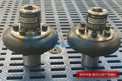
To understand why the flexible coupling is treated as the core of the transmission rather than as an incidental accessory, it helps to examine what a coupling actually does in a PU panel line drive. The motor—whether asynchronous, servo, or geared—delivers torque at a controlled speed. The gearbox reduces that speed and multiplies torque to match the roller's demand. But the gearbox output shaft and the roller input shaft are two separate pieces of rotating machinery, each supported by its own bearings, each mounted on its own structure, and each subject to its own thermal and dynamic behavior. The coupling bridges the gap between them. In a rigid coupling, the two shafts would be forced into perfect collinearity, and any deviation would create bending moments, side loads, and stress concentrations that accelerate wear. In a flexible coupling, an elastomeric element—often a polyurethane or rubber tire, an elastomeric insert, a bellows, or a disc pack—deforms within its elastic range to accommodate the relative movement while still transmitting torque. The crucial point for a continuous PU sandwich panel line is that this deformation must be predictable and repeatable across millions of cycles. If the coupling wind-up (the angular twist under torque) is too large, the phase relationship between adjacent rollers drifts, and the panel liner may be stretched or compressed between stations. If the coupling backlash is nonzero, the line can exhibit momentary slip during direction reversals or torque reversals, which in a continuous process translates directly into visible marks on the facing sheet.
Misalignment in a continuous PU sandwich panel line comes in several distinct forms, and each places a different demand on the flexible coupling. Angular misalignment occurs when the two shaft centerlines intersect at a small angle rather than being collinear; this is the most common form and typically arises from imperfect shimming during installation or from uneven settling of the machine base. Parallel, or offset, misalignment occurs when the two shafts are parallel but displaced sideways; this is particularly common in long roller tables where the drive motor is mounted on a side platform and the roller shaft extends out to the line, and where thermal expansion shifts the roller axially relative to the motor. Axial misalignment—the end float of one shaft relative to the other—is caused by thermal expansion of the roller itself, which lengthens as it heats up and must push into or pull away from the coupling without binding. A well-selected flexible coupling in this environment must accommodate all three simultaneously, because in reality these offsets are never present in isolation. Moreover, the coupling must accommodate them not as a one-time installation tolerance but as a continuous, dynamic, ever-changing envelope. The offset that exists at steady-state temperature is not the same offset that exists during a rapid line speed change, a sheet splice, or a foam-formulation shift that changes the reaction pressure. The coupling therefore operates as a compliant joint that must remain within its elastic deflection envelope across the entire operating window of the line.
Torque transmission in a continuous PU sandwich panel line is far from steady. The line consists of many driven elements, each with its own inertia and its own load characteristic. The lamination belt, for instance, must drag the panel through the curing oven against friction and against the expanding foam pressure. The cut-off saw must accelerate to line speed, make a transverse cut, and decelerate, all within a fraction of a second. The unwinder must maintain constant tension as the coil diameter decreases. Each of these loads presents a different torque profile to its drive, and the coupling is the mechanical interface that must transmit these torques smoothly. In a flexible coupling, torque is transmitted through the elastic element, which means that the torque reaches the driven shaft slightly delayed and slightly smoothed. This smoothing effect is beneficial in a continuous panel line: it dampens the torque pulses that would otherwise transmit from the gearbox output into the roller, and it prevents abrupt load changes from shocking the motor windings. But the coupling must be chosen so that its torsional stiffness is high enough to maintain positional accuracy between the drive and the load. In a panel line where adjacent rollers must remain phase-synchronized to within a fraction of a degree, a coupling with excessive wind-up will introduce a speed-dependent phase lag that accumulates across the line. The art of coupling selection in this application is therefore a balancing act: enough compliance to absorb misalignment and dampen shock, but enough torsional rigidity to preserve the synchronization that the panel quality demands.
The direct impact of coupling performance on the quality of the finished PU sandwich panel is often underappreciated. The facing sheet must enter the lamination zone flat, evenly tensioned, and traveling at exactly the same speed as the upper and lower belts. If a coupling on one roller introduces a momentary speed ripple, the facing sheet will be stretched at that point, creating a longitudinal wave that will be captured between the liners and the foam core and remain visible in the finished panel as a lengthwise wrinkle or thickness variation. If a coupling on the curing tunnel rollers allows a slight angular displacement to transmit into the roller, the roller will run with a slight axial wobble, which drags the panel sideways and causes edge wave or uneven foam density. If a coupling has backlash, the line's tension control loop sees a momentary loss of traction at each torque reversal, and the tension regulator overshoots, producing a tension band that shows up as a gloss variation or a coating defect on the prepainted steel. Conversely, a properly matched flexible coupling—one with the right elastomer shore hardness, the correct torque rating, and adequate misalignment capacity—hides all of these imperfections from the product. The panel simply exits the line with uniform thickness, flat surfaces, and consistent bond strength, and the operator never sees the coupling working. This invisibility is precisely the mark of a good coupling: it is the silent enabler of process stability.
Vibration damping and dynamic response are further dimensions in which the flexible coupling functions as the core of the transmission. A continuous PU sandwich panel line is a distributed-mass mechanical system with many rotating elements, each contributing its own natural frequency. When the line passes through a speed that excites a structural resonance—for instance during a ramp-up from threading speed to production speed—the resulting vibration can be severe if it is not isolated. A rigid coupling would pass this vibration straight through between the motor and the roller, amplifying it at the bearing supports and potentially exciting the entire frame. A flexible coupling, by contrast, introduces a compliant element that shifts the natural frequency of the drive train away from the operating range and dissipates vibrational energy as small amounts of heat in the elastomer. In a PU panel line, this damping role is especially valuable because the process is sensitive to micro-motion: a vibration at the lamination belt can create a periodic variation in the gap between the belts, which the expanding foam will faithfully reproduce as a periodic thickness wave in the panel. By absorbing vibration before it reaches the process rollers, the coupling acts as a mechanical low-pass filter on the drive train. The selection of coupling type—elastomeric tire, jaw-type, disc-pack, or bellows—depends heavily on the damping requirements and the torsional precision requirements of the specific drive position.
Maintenance and service life considerations further cement the flexible coupling's central role. In a production line that is expected to run for shifts, weeks, and months, the coupling is the wear element of the drive train. The elastomer insert flexes millions of times per day, and eventually it fatigues, cracks, or loses its elastic properties. The great advantage of a correctly designed flexible coupling in a PU panel line is that this wear is predictable and can be inspected without disassembling the entire drive. Many coupling designs allow the elastomeric element to be replaced in place, with the motor and roller left in their installed positions. This is a critical operational advantage in a continuous production environment where unplanned stoppages are extremely costly. Moreover, because the coupling absorbs misalignment, the bearings, seals, and gear teeth on either side of it experience far less side load than they would in a rigid arrangement. This translates directly into longer bearing life, fewer oil leaks, and longer gearbox overhaul intervals. The coupling thus functions as a sacrificial component that protects the much more expensive capital equipment around it. When a coupling is undersized or misapplied, the failure mode is not graceful: a torn elastomer can dump the roller to free rotation, producing a panel jam in the oven, or a sheared coupling bolt can let the drive disconnect mid-panel, wasting meters of product and requiring a lengthy cleanup. The coupling therefore carries both a protective role and a reliability role.
Viewed at the system level, the flexible coupling is not a line item but a design variable that interacts with every other element of the drive train. The selection of motor inertia, gearbox ratio, roller diameter, belt tension, and control loop tuning all interact with the coupling's stiffness and damping characteristics. A coupling that is too soft for a given inertia ratio will allow torsional oscillation that the speed controller cannot damp out, resulting in speed hunts that appear as panel thickness bands. A coupling that is too stiff will transmit every bit of misalignment into the bearings, shortening their life and introducing audible noise. A coupling that is over-torqued for the application will be unnecessarily expensive and bulky; one that is under-torqued will fatigue prematurely. In a continuous PU sandwich panel line, where the drive train is replicated across dozens of positions, the coupling choice is multiplied across the machine. Choosing the right coupling at each position—heavy-duty for the main lamination drives, precision-type for the edge-band and web-guiding drives, high-damping for the cut-off saw drive—is an exercise in systems engineering. It requires understanding not only the static torque and speed of each position but also the dynamic loading, the thermal environment, the maintenance access, and the product quality sensitivity. This is why the flexible coupling, though small, is rightly regarded as the core of the transmission: it is the element through which all other drive-train decisions are reconciled into physical motion.
In summary, the continuous PU sandwich panel manufacturing line is a machine defined by synchrony, flatness, and uninterrupted motion, and the flexible coupling is the component that makes those qualities mechanically achievable. It bridges the unavoidable geometric gaps between shafts that thermal expansion, structural deflection, and installation tolerance create; it transmits the fluctuating torque of foam-laden rollers and cycling cut-off saws without shock or backlash; it dampens the vibrations that would otherwise ripple through the facing sheets; and it protects the bearings, gearboxes, and motors from the side loads that a rigid connection would impose. The coupling operates invisibly, and that invisibility is the measure of its success: when the line produces panels of uniform thickness, flat surfaces, and consistent bond quality shift after shift, the coupling has done its job. Conversely, when panels develop longitudinal waves, edge marks, or thickness bands, the coupling is very often the first place to look. It is the small, elastic, wear-prone, but indispensable heart of the transmission system—the element that converts the theoretical synchrony of electric drives into the physical reality of a perfectly formed sandwich panel. For engineers who design, operate, or maintain continuous PU panel lines, treating the flexible coupling as a core design variable rather than as an afterthought is the difference between a line that merely runs and a line that runs well.