Application Points Of Flexible Coupling In Continuous PU Sandwich Panel Production Line
In any continuous polyurethane sandwich panel production line, the mechanical heart of the system lies in how rotational motion is transmitted from motors and gearboxes to the dozens of rollers, belts, spindles, and feeders that shape, move, and finish the panel as it travels along the line. A flexible coupling sits at every one of these junctions, yet it is rarely the component that draws attention until something goes wrong. Its job is to connect two shafts that cannot be perfectly aligned in practice—whether the misalignment arises from manufacturing tolerances, thermal expansion during warm-up, settling of the frame, deflection under load, or simply the difficulty of holding multiple long rollers to a common centerline across a line that may stretch more than a hundred meters. Without the right coupling at each of these points, the line would suffer premature bearing failure, vibration that scars the panel surface, backlash that distorts the foam core, and frequent unplanned stops. Understanding where and why flexible couplings are used in this specific equipment is therefore not a theoretical exercise; it is the difference between a line that holds tolerance for years and one that spends more time in the maintenance bay than in production. The continuous PU panel line is particularly demanding because the process combines three very different materials—inner and outer metal skins, usually steel or aluminum, and a reactive polyurethane foam that expands in seconds—into a single rigid laminate at high speed. Each stage of the line imposes its own misalignment signature, torque pattern, speed range, and environmental exposure, and the coupling at each point must be selected and installed to match that signature.
The first critical application point is the high-pressure mixing head drive, which is the chemical heart of the line. The polyol and isocyanate components are metered, mixed at extremely high rotational speeds, and poured onto the lower moving skin as it passes under the head. The agitator spindle inside the mixing head rotates at several thousand revolutions per minute, often driven through a small but precisely balanced motor and coupling arrangement. Because the spindle is long and slender, and because the chemical mixture creates both frictional drag and occasional sudden loads when the blend ratio shifts, the coupling here must accommodate angular misalignment between the motor shaft and the spindle while maintaining near-zero backlash and excellent dynamic balance. A helical beam coupling or an Oldham-style disk-type coupling is commonly chosen at this point because it can handle small but real misalignment without introducing runout, and because it transmits torque smoothly even when the motor accelerates and decelerates between pour cycles. Any play at this coupling translates directly into inconsistent shear of the chemical stream, which shows up as uneven foam density, streaks, or voids in the finished panel. The coupling also has to withstand occasional chemical splashes and the thermal environment around the pouring zone, which means its materials—usually aluminum hubs with stainless or engineering-element flex members—are chosen for corrosion resistance rather than raw strength alone.
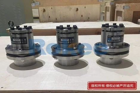
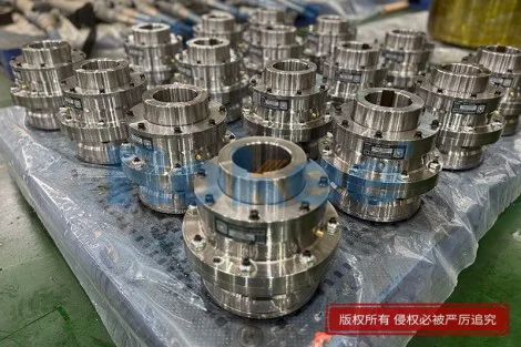
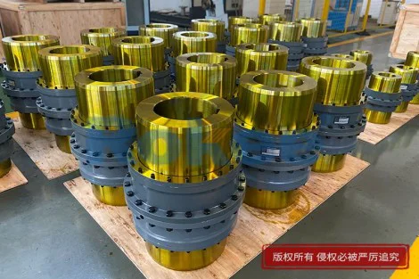
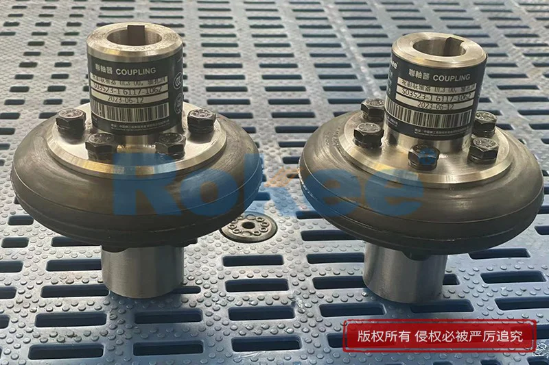
Moving downstream, the double-chain or pin-chain conveyor that carries the sandwiched panel through the laminating section is the next major coupling application. This conveyor consists of two long parallel tracks, each driven by a gearmotor connected through a drive shaft and a set of sprockets. Because the track is so long, the steel structure expands when the line heats up during operation and contracts when it cools, and the two tracks may not expand at exactly the same rate because one is closer to the oven. A rigid coupling between the gearbox output shaft and the drive sprocket would bind under these thermal shifts, creating huge side loads on the sprocket bearings and the gearbox output shaft. A flexible coupling—typically a tire coupling, an elastomer jaw coupling, or a dise pack coupling—absorbs this axial movement and angular offset while still transmitting the high torque needed to pull a full panel stack through the laminator. The coupling also acts as a shock absorber when the line starts up under load, or when a heavy panel bundle enters the oven and the drag suddenly increases. This dampening effect protects the gearbox, which is usually the most expensive and most fragile component in the drive train, from torque spikes that can strip gears or shear keys.
The laminating rollers themselves, which press the upper and lower skins together around the expanding foam, represent another cluster of coupling points. Each roller is driven either individually by a small gearmotor or grouped in pairs through a line shaft. Because the rollers are long, thin, and loaded across their entire width by the pressure of the foam expansion, they bend slightly during production, and their end shafts deflect relative to the motor shafts. A rigid connection would force the roller bearings to carry this deflection, generating heat and wear. Flexible couplings at each roller drive allow the small angular and parallel misalignment caused by roller bending to be absorbed within the coupling rather than transferred to the bearings or the motor. The coupling must also be torsionally stiff enough to maintain accurate speed matching between adjacent rollers; if one roller slips or lags, the surface of the metal skin is scratched, or the foam core is sheared before it cures. Elastomer insert couplings are popular here because they combine good misalignment capacity with modest torsional stiffness and are inexpensive to replace when the elastomer fatigues. In high-speed lines where speed matching is critical, disc pack couplings may be used instead, accepting a higher purchase cost for better torsional rigidity and longer service life.
As the panel leaves the laminator and enters the curing oven, the drive system changes character again. The oven zone is hot—often well above the ambient workshop temperature—and any coupling located inside or near the oven must retain its mechanical properties at elevated temperature. Elastomer couplings, which rely on rubber or polyurethane flex elements, are a poor choice in this zone because the heat softens the element, leading to premature fatigue and loss of damping. Instead, metal-flexing couplings such as disc pack designs or bellows couplings are specified, since they contain no organic flex material and can operate at oven temperatures without degradation. The coupling here also has to handle the thermal expansion of the long conveyor beams inside the oven, which can shift the drive shafts axially by several millimeters compared with the cold state. A coupling designed with sufficient axial travel, or installed with an appropriate sliding fit between the shaft and hub, prevents binding. The torque loads in the oven conveyor are relatively steady because the panel has already cured and simply needs to be transported, so the coupling does not need high shock absorption, but it does need reliability over long hours of continuous operation in a hot, dusty environment.
The transverse cutting saw, which slices the continuous panel into predetermined lengths as it exits the line, is one of the most demanding coupling applications on the entire line. The saw must accelerate to match the panel speed, traverse with the panel while cutting through the metal skins and foam core, then retract and return to the starting position. The main saw blade spindle rotates at high speed, driven by a motor that is itself mounted on a moving carriage. The coupling between the saw motor and the blade spindle must tolerate the misalignment inherent in a moving carriage system, where mounting bolts may loosen slightly over time and where the carriage rails wear. It must also transmit high torque instantaneously, because cutting through two steel skins and a thick foam core creates sudden, high-impact loads. A jaw-type elastomer coupling or a bellows coupling is commonly used here, selected more for its ability to handle shock and for easy replacement than for extreme precision. Equally important is the coupling that drives the traverse motion of the carriage itself, which may use a rack and pinion or a ball screw. That coupling must be backlash-free to ensure the cut length is accurate to within a millimeter or two, because the cut length directly determines the customer's panel dimensions. A zero-backlash coupling at this point ensures that every panel comes out to the specified length, and that the saw does not drift during the cut, which would produce a ragged or angled edge.
After cutting, the panels enter the edge trimming and finishing section, where the sides are trimmed to width, and where optional features such as tongue-and-groove joints or sealant grooves may be machined. The trimming spindles rotate at very high speed, often in the tens of thousands of revolutions per minute, and they must run with extreme precision because any runout at the cutter shows up as a wavy or uneven edge on the panel. Flexible couplings at these spindles are almost invariably bellows-type or miniature beam couplings, chosen for their zero-backlash, high concentricity, and ability to handle small amounts of misalignment without introducing runout. The coupling here is more about precision than strength; the torque required to drive a trimming cutter is modest, but the accuracy requirement is severe. Because the cutters are changed frequently as panel profiles change, the coupling must also be easy to disassemble and reassemble without disturbing the alignment of the spindle. Many installations use split-clamp hubs on these couplings so that the cutter can be swapped without sliding the motor or the spindle along its shaft. This saves valuable setup time between panel runs, which is important because changeovers on a continuous line are pure downtime.
The stacking and destacking system at the end of the line handles the finished panels, lifting them off the conveyor and arranging them into bundles for packaging. The drives in this section are characterized by frequent starts, stops, reversals, and varying loads—an empty lifting arm accelerates quickly, while a loaded stack moves more slowly. Flexible couplings in this section serve primarily to absorb shock and to tolerate misalignment in what is often a more lightly built frame, because the stacking machinery is less rigid than the main production line. Jaw couplings with a urethane insert are typical here, as the urethane element dampens the reversing shocks and can be replaced in seconds when it wears. The couplings also protect the gearboxes and motors from the occasional impact that occurs when a panel is mis-fed or when the stacker collides with an unexpected obstruction. In this part of the line, coupling selection is driven by economics and maintainability rather than by precision, because the tolerances of the stacking operation are loose compared with the forming and cutting stages. A simple, inexpensive, easily replaceable coupling is the right choice, and over-specifying with a high-precision disc pack would waste money without improving panel quality.
Beyond these specific machines, flexible couplings play a quiet but essential role in the ancillary systems that keep the line running. The hydraulic power units that supply the laminator pressure and the saw traverse use flexible couplings between the electric motor and the hydraulic pump; these couplings must handle the pulsating torque of the pump and tolerate the misalignment that results from the pump and motor being mounted on separate baseplates. The coolant circulation pumps, the exhaust fans that remove fumes from the pouring zone, the lubrication pumps, and the drive for the packaging strapping machine all rely on flexible couplings. In each case, the coupling absorbs the misalignment that would otherwise cause premature seal failure, bearing wear, and vibration. Many of these ancillary drives are small and inexpensive, but their failure can stop the whole line, because the cooling fan stops, or the lubrication alarm trips, or the hydraulic pressure drops. The coupling here is often the most vulnerable component in the drive train, because it is the element designed to wear first—acting as a mechanical fuse that protects the more expensive pump and motor. Routine inspection and scheduled replacement of these small couplings prevent cascading failures that could otherwise take the line down for hours.
Finally, the long-term reliability and maintainability of the entire continuous PU sandwich panel line depend on thoughtful coupling selection, installation, and inspection practice. Every coupling on the line should be treated as a wearing component with a predictable service life, and the maintenance schedule should include regular checks of elastomer elements, bolt torque, alignment, and any signs of fretting or corrosion on metal flex elements. When a coupling fails in service, it almost never fails quietly; it announces itself through vibration, noise, heat, or a visible change in panel quality, and the operator who knows which coupling serves which machine can diagnose the problem quickly. Proper installation is as important as proper selection: even the best coupling will fail early if it is installed with excessive misalignment, if the shafts are not centered, or if the hubs are not tightened to the correct torque. Alignment should be checked after the line has reached operating temperature, because thermal expansion shifts the shaft positions and can turn a cold-aligned installation into a hot-misaligned one. Over the years, a well-maintained set of flexible couplings—chosen to match the torque, speed, misalignment, temperature, and precision requirements of each specific point on the line—becomes one of the most cost-effective reliability investments in the entire production system. It protects the expensive gearboxes, motors, spindles, and bearings, it preserves the tight tolerances that define a quality PU sandwich panel, and it reduces the unplanned downtime that ultimately determines whether a line is profitable. The coupling may be a small and unassuming component, but in a continuous production line that runs twenty-four hours a day, its correct application at every critical point is what keeps the line moving.