Maintenance Of Flexible Coupling For Continuous PU Sandwich Panel Production Line

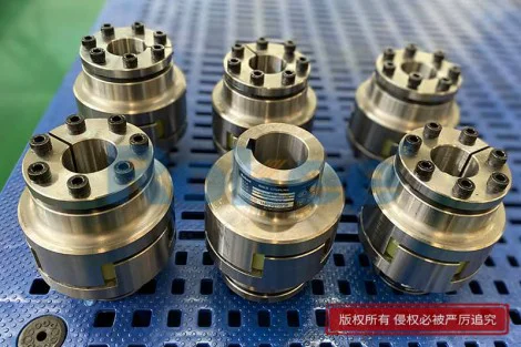
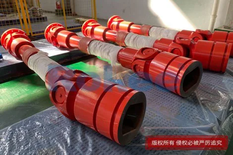
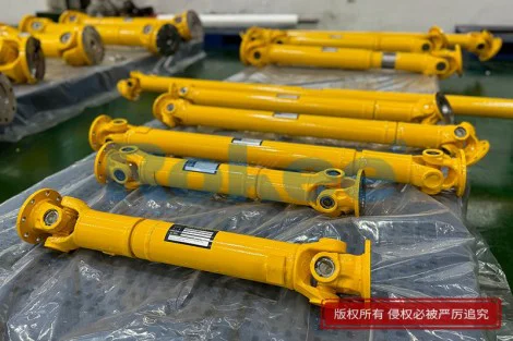
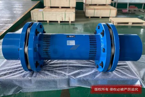
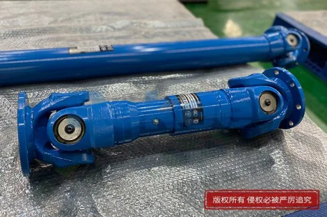
A continuous polyurethane sandwich panel production line is a long, tightly integrated machine in which unwinding, chemical dosing, foaming, double-belt curing, cutting and stacking happen without interruption. Along this line, flexible couplings sit at almost every point where power must cross a gap between a driving unit and a driven unit: between the main drive motor and the reducer, between the reducer output shaft and the conveyor belt drum, between the high-pressure metering pump and its drive, between the trimming saw spindle and its motor, and between the lifting table or outfeed roller conveyor and its gearmotor. Although a coupling is a relatively small component compared with the belt oven or the foaming head, its role is disproportionate. It must transmit torque reliably while tolerating the small but unavoidable offsets between shaft centers, absorbing the slight angular and parallel misalignment that arises from thermal expansion, foundation settling and ordinary assembly tolerances. At the same time, it cushions shock loads, dampens torsional pulses from start-stop cycles and protects adjacent bearings, seals and gear teeth from forces they were never designed to carry. On a PU panel line, the coupling also bridges units that deliberately sit at different temperatures: the motor outside the heated zone, the drum near the curing oven, the pump on a vibrating skid. A good flexible coupling is therefore a silent buffer between two imperfect worlds, and the maintenance program is what keeps that buffer from becoming the weakest link. When a coupling on this kind of line fails, the consequences cascade quickly. A torn elastomer element can throw a drive out of phase, producing uneven belt speed and visible panel defects such as thickness variation, skin delamination or deformed edges. A fractured disc pack can drop a driven shaft to rest mid-cure, trapping half-finished panels inside a heated belt where they will scorch or stick. A loose bolt can spin out and strike nearby guards, wiring or operator walkways. Unplanned stops on a continuous line are costly not only because of lost output but because restarting a warm oven, rebalancing chemical ratios and re-syncing facing payoffs consumes hours. The restart itself introduces risk: a cold pull-away can scratch the belt, a sudden foaming start can flood the mixing head, and a mis-synchronized payoff can produce a panel that has to be scrapped from end to end. For these reasons, coupling maintenance on a PU sandwich panel line is not peripheral housekeeping; it is one of the small, high-leverage habits that separate lines that run steadily for months from lines that bleed output through repeated short stoppages. The couplings that deserve the most attention are not the ones in the cool, clean motor room but the ones that sit beside the oven, the saw and the chemical pump, because those are the couplings that see heat, load and contamination every shift.
The environment in which these couplings work is unusually hostile, and any maintenance plan must start from that reality rather than from a generic rotating-equipment checklist. Near the foaming and curing section, air temperature can rise well above ambient, and radiant heat from the oven walls warms coupling hubs that sit on the line side of the belt. Polyurethane reaction itself releases heat, and the chemical stream carries traces of polyol, isocyanate and blowing-agent fumes that drift into drive areas, condense on cooler metal and gradually attack rubber, synthetic elastomers and unprotected fasteners. Release-agent overspray, dust from facing materials such as aluminum foil, galvanized steel coil and glass fiber tissue, and fine polyurethane overspray all settle on coupling guards and find their way through small gaps into the coupling itself. On the saw and cutter stations, loads are far from steady: a trimming saw accelerates through a steel facing, stalls briefly when the blade tooth load peaks, and then runs light until the next cut, producing a pulsating torque that flexes the coupling on every stroke. The main belt drives, by contrast, run at nearly constant speed but carry a slowly rising thermal load as the oven reaches temperature, which shifts shaft alignment by fractions of a millimeter over the course of a shift. Lifting tables and stackers reverse direction repeatedly, so their couplings see frequent torsional reversals and axial thrusts. The metering pumps run at precisely controlled low speeds where even a minute torsional ripple translates into a visible dosing imperfection, so the coupling on that pump must dampen rather than transmit every small motor fluctuation. Over months, this combination of heat, chemical haze, abrasive dust, pulsating load and thermal growth degrades coupling materials in predictable ways: elastomers harden and crack, grease loses its consistency and turns varnish-like, metal discs develop fatigue cracks at bolt holes, and fasteners loosen through micromotion. The grease in a grid or gear coupling exposed to isocyanate mist can actually become abrasive as the mist cures inside the joint, turning a lubricant into a lapping compound that wears the teeth it was meant to protect. A maintenance program that ignores these ambient factors will either over-maintain couplings in clean, cool motor rooms or under-maintain couplings exposed to oven-side heat and chemical mist, and both errors show up eventually as premature failures. The practical response is to divide the couplings on the line into environmental groups, and to assign shorter inspection and replacement intervals to the ones that work near heat, chemicals or pulsating loads, while allowing the clean, steady drives a more relaxed rhythm.
The first and cheapest layer of coupling maintenance is the routine visual and auditory inspection that operators and line attendants can perform during normal rounds, without tools and without stopping the line. On each walk along the drive side, the technician should glance at every coupling guard and listen. A healthy coupling on a running line is silent, or at most produces a low, even hum that is indistinguishable from the adjacent motor and gearbox. A new noise, even a faint one, is already information: a squeal often points to a dry elastomer element running without enough clearance or to a sheared elastomer spider that has shifted; a rattle or metallic knock suggests a loose bolt, a fractured grid or a worn gear tooth beginning to hammer; a rhythmic thump once per revolution can indicate a cracked disc or a sheared pin that is catching on each rotation. The eye should look for grease or oil weeping from under guards, for discoloration of metal near a coupling that would indicate overheating, for obvious wobble of the half-coupling relative to its hub, and for fragments of rubber or metal lying on the skid beneath the drive, which is often the first tangible sign that a flexible element is shedding material. Temperature can be judged cautiously by the back of the hand held near, not on, the guard, or better with an infrared thermometer pointed at the hub; a coupling that runs noticeably hotter than the adjacent bearing housing, or that climbs steadily over a shift, is sending a message even before a measured threshold is crossed. Vibration transmitted through the guard wall can be felt with a palm, and a sudden roughness compared with yesterday's feel is worth logging. The condition of the guard itself is also part of the check: a guard that is bent, loose or missing bolts no longer contains flying fragments, and a guard interior caked with polyurethane overspray is a sign that the seal between guard and coupling is no longer doing its job. Every observation, however small, should be written into the maintenance log with date, shift, drive identification and a short note, because a single odd reading is noise but a trend of three similar readings is a diagnosis. The log should also record what normal sounds and temperatures actually are for each drive, because a new technician walking the line has no way to know that a particular saw coupling has always hummed slightly unless the baseline is written down. The point of this daily layer is not to replace precision measurement but to catch the beginning of a problem at the moment when a guard can be opened and a simple fix made, rather than waiting for a catastrophic failure that forces an unplanned line stop in the middle of a production run. Operators who are trained to notice the small signs become the most reliable early-warning system on the entire line.
Beyond sight and sound, the single most powerful maintenance action for a flexible coupling on a continuous line is careful shaft alignment, because a large share of premature coupling wear is caused not by age but by the two shafts not sharing the same centerline. Misalignment comes in three familiar forms: parallel offset, in which the two shaft centers sit beside each other; angular misalignment, in which the shafts are tilted relative to one another; and axial end float, in which shafts push toward or pull away from each other. On a PU panel line, alignment drifts for concrete reasons: the concrete foundation under heavy ovens settles unevenly, the gearbox shifts slightly on its mounting feet after a year of vibration, the motor moves when its belt is re-tensioned, and the oven-side drum expands thermally several millimeters during warm-up. A coupling can tolerate only a finite amount of this offset, and when the offset exceeds the flexible element's design envelope, every revolution bends the elastomer or flexes the disc beyond its intended travel, shortening life dramatically and pounding the adjacent bearings. The checking procedure starts with the line stopped and locked out: foundation bolts are checked for tightness, feet are checked for soft foot by rocking the motor on its mounts, and a rough straightedge and feeler-gauge check between the half-couplings gives an immediate sense of whether a gross problem exists. For critical drives such as the main belt and the metering pump, a dial-indicator setup or, preferably, a laser alignment instrument is used to measure offset and angularity at the coupling rim and face, then shims are placed under motor feet or positions adjusted until the readings fall within the coupling's usable tolerance at operating temperature. Because thermal growth changes the numbers, experienced crews either align hot after a warm-up or apply a deliberate offset at cold so that the shafts meet when hot; this is especially important for the belt drum drive, where the drum center rises measurably as the oven reaches its setpoint. Alignment should be rechecked after any foundation repair, after a motor or gearbox replacement, after a major skid modification, and on a scheduled interval tied to operating hours rather than calendar months, because a line that runs two shifts a day misaligns its shafts far faster than a line that runs one. A common mistake is to align a coupling in the morning cold, declare it correct, and then let the line reach operating temperature without re-checking; by mid-shift the thermal growth has moved the drum, and the coupling is running badly misaligned for eight hours a day. The other common mistake is to assume that a flexible coupling tolerates unlimited offset and therefore needs no alignment at all; in reality, flexibility is a compensation for small residual errors, not a license for large ones, and every millimeter of excess offset is paid back in shortened element life and increased bearing load.
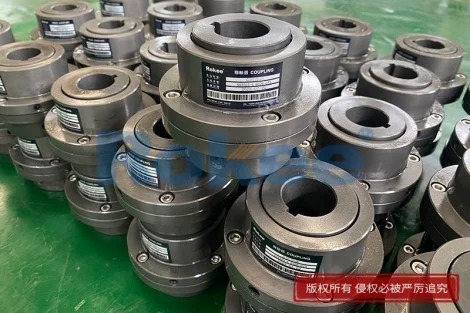
Lubrication is the next pillar, but it must be matched to the coupling type rather than applied as a blanket rule. Many flexible couplings used on modern panel lines are elastomeric: a rubber or polyurethane spider, tire, sleeve or jaw element that transmits torque through compression and needs no grease at all. For these, lubrication maintenance means keeping petroleum oils off the element, because hydrocarbon fluids swell rubber and accelerate aging, and wiping clean any release-agent overspray that lands on the flexible part. Grease-filled couplings are a different matter: gear-type couplings, in which two hubs mesh through internal and external teeth, and grid-type couplings, in which a spring grid sits in milled slots on both halves, rely on a continuous film of grease to prevent metal-to-metal wear between moving surfaces. On a PU line, the grease inside these couplings faces heat, chemical mist and a slowly expanding population of dust particles, and it thickens, dries out or washes out over time. The maintenance task is therefore to purge and replace the grease on a schedule tied to operating hours, to use a grease compatible with the coupling's internal materials and rated for the temperatures the hub actually reaches, and to avoid both under- and over-greasing. Under-greasing lets the gear teeth or grid run dry, which shows up as scoring, discoloration and, eventually, tooth breakage; over-greasing forces grease past the seals, contaminates the surrounding area and can generate heat as the churned grease shears itself. The right procedure is to stop and lock out the drive, clean the grease fitting and its surrounding area so that no dust is pushed in, attach the gun and pump fresh grease slowly until clean grease emerges from the relief opening, then wipe away the expelled film and note its condition in the log. The color and texture of old grease tell a story: blackened or varnished grease points to heat damage, water-fogged emulsion points to washout, metal-flaked grease points to internal wear, and grease mixed with polyurethane overspray points to a seal that has failed. Each lubrication event, with product type and date, is recorded, and the next due date is calculated from operating hours rather than from the wall calendar. On a PU line, the choice of grease also matters for chemical resistance: a standard general-purpose grease that handles clean water fine may not stand up to isocyanate and polyol fumes, and a grease that is excellent for a cool grid coupling may soften and drip out when the hub sits beside an oven. It is worth keeping a small stock of the correct grease on the premises, because mixing an off-the-shelf product from the maintenance cupboard with an unfamiliar coupling can turn a routine lubrication into a seal-swell event. Finally, the coupling guards should be closed and sealed after each lubrication, because an open guard invites the very dust and overspray that the grease film is supposed to be protected from.
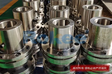
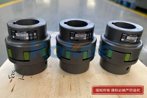
Wear monitoring of the flexible element itself is where the coupling's service life is actually managed, and it requires the guard to be opened and the element examined directly. For elastomeric spider, tire and sleeve couplings, the inspector looks for several specific failure signatures: surface cracking, especially in the root region where the flexing is greatest; compression set, meaning the element no longer springs back to its original shape and sits slack in the jaws; swelling, where the material has absorbed oil or chemical and grown soft or tacky; hardening, where the rubber has lost its elasticity and rings when tapped with a screwdriver handle; and missing chunks, where a section has torn out and been thrown. Any of these conditions is a reason to replace the element, because a degraded elastomer no longer cushions shock and can fail without warning mid-shift. On a PU line, the most common elastomer killer is chemical attack: a spider that looks intact but has absorbed isocyanate fumes will have turned brittle inside, and a careful technician can detect this by bending a small corner or by comparing the element's hardness to a new spare. For disc-pack couplings, in which thin stainless-steel discs bolt alternately between two hubs, inspection focuses on the bolt-hole regions where fatigue cracks typically start, on any discoloration that would indicate overheating or bolt friction, and on the tightness of the through-bolts; a disc with a visible hairline crack at a hole must be replaced, and a set of discs should always be replaced as a matched set rather than mixing new and old, because mismatched discs share load unevenly and the weaker one fails first. For grid couplings, the spring grid is examined at its ends and at every slot exit, where bending fatigue is concentrated, and the grid is replaced if it shows a visible kink, a crack at a bend, or fretting wear that has thinned it noticeably. For gear couplings, the tooth backlash is felt by rocking one hub against the other with the coupling immobilized, and excessive play indicates that the teeth have worn past their useful life. Wear thresholds are set from the coupling's own assembly information and from experience on this specific line, not from generic tables: a line that has seen three elastomer failures in six months at a certain drive has learned something about that drive's load and environment, and that knowledge should be encoded into the replacement criterion. Because flexible elements are relatively inexpensive compared with a line stop, the maintenance philosophy on a PU panel line is usually to replace on evidence of wear rather than to run an element to failure; spare spiders, tires, disc packs and grids for every critical coupling are kept in the on-site store, with the part number and location recorded, so that a planned mid-shift repair takes minutes rather than hours. A useful discipline is to keep the old element after replacement, lay it beside the new one, and photograph the failure mode; over a year, these photographs become a visual catalog that helps technicians recognize early signs next time and helps the maintenance engineer judge whether the current element life is acceptable or whether a root problem is shortening it.
Fastener integrity is the quiet subject that many otherwise thorough maintenance programs overlook, yet a loose coupling bolt is one of the most common causes of sudden coupling failure. Coupling bolts are not ordinary bolts: they transmit the entire torque of the drive through a small shear or friction surface, and they vibrate constantly in service. On a continuous PU line, the coupling on a trimming saw, a belt drum or a metering pump sees thousands of load reversals per shift, and a bolt that was correctly torqued at assembly can lose its preload through micromotion, settle into the joint and eventually back itself out. The maintenance task is therefore twofold: verify tightness on a schedule and verify condition on a schedule. Tightness is checked with a properly calibrated torque wrench, comparing the applied torque to the value specified during assembly, and on new or recently assembled couplings a re-torque after the first run-in hours is essential because the joint surfaces seat and the initial preload drops. Condition means looking at each bolt and nut for thread damage, for corrosion that has locked the nut in place, for elongation visible as necking, for a sheared half of a bolt that has already failed but is still holding on by a fragment, and for missing or broken locking features such as distorted lock washers, cracked nylon insert nuts or severed safety wires. Keyways and set screws are examined too, because a key that has shifted in its seat can translate vibration into the coupling hub and wear the bore oval. On disc-pack and grid couplings, the friction bolts that clamp the pack are especially sensitive to under-torquing, which lets the discs slip and frets the holes; on elastomeric jaw couplings, the set screws that lock the half-coupling onto the shaft must be checked because a slipped hub will tear the spider instantly. Vibration loosening is a physical phenomenon that no amount of initial torque permanently cures, so the program must include periodic re-checks, and when a bolt repeatedly loosens at the same location, the root cause is investigated rather than the bolt simply retightened: a worn bore, a bent shaft, a soft foot or an undersized bolt are the usual culprits. On a PU line, there is an additional wrinkle: polyurethane overspray can glue a nut in place so that it reads as tight when measured, while the preload has actually long since relaxed; for this reason, a torque check on a contaminated drive should include visually confirming that the bolt has not turned in its hole, and any bolt that shows a cured-overspray crust should be cleaned and re-torqued rather than trusted. Safety wires, where used, are replaced fresh whenever a coupling is opened, because a wire that has been bent once loses its elasticity and can no longer absorb the small motions that try to unwind the nut. The whole fastener routine is unglamorous, but a single bolt that backs out on the main belt drive is enough to stop the line for a shift, which makes ten minutes of scheduled bolt checking one of the best return-on-investment tasks in the maintenance program.
Once the line has been running long enough to establish a baseline, temperature and vibration monitoring turn coupling maintenance from a calendar-driven task into a condition-driven one. The principle is straightforward: a healthy coupling produces a characteristic vibration signature and a characteristic temperature rise, and any deviation from that baseline is an early warning. Baseline readings are taken when the coupling is new, freshly aligned and freshly lubricated, with the line at normal operating speed and load, and they are recorded as a reference point. Vibration measurements are taken at the bearing housings and, where accessible, at the coupling guard, using a handheld vibration meter that captures overall velocity; for deeper diagnosis, the signal is analyzed on a spectrum, and the pattern of peaks reveals the underlying cause: a strong peak at one times the rotational speed often points to misalignment, peaks at two times speed point to looseness, and inner- and outer-race frequencies point to bearing trouble that may be transmitted to the coupling. Temperature readings are taken with an infrared gun on the hub surface, or with permanently mounted sensors on the hottest drives, and compared with the baseline and with the ambient temperature. A coupling that warms up more than expected after a fresh lubrication may simply have been over-greased and needs time to settle, but a coupling that warms up week after week in the same direction is developing internal friction from wear. Trending over weeks and months is more valuable than any single reading: a coupling whose vibration creeps up by a modest percentage each month is wearing steadily and can be scheduled for the next planned window, whereas a coupling whose vibration doubles overnight has developed a crack and needs immediate attention. Alarm and shutdown thresholds are set relative to this line's own baseline rather than to universal numbers, because a small drive at high speed naturally vibrates more than a large drive at low speed, and a coupling near an oven naturally runs hotter than one in a cool motor room. Data is logged in a simple spreadsheet or in a maintenance management system, and the trend lines are reviewed at the monthly maintenance meeting. When a reading crosses its threshold, the response is predefined: an operator may be asked to watch the drive, a technician may be sent to open the guard at the next stoppage, or the line may be slowed and the coupling inspected before the failure propagates to the adjacent gearbox or bearing. On a PU panel line, the metering-pump coupling is the most sensitive measurement point, because a dosing imperfection caused by a coupling resonance shows up as a visible panel quality issue long before it shows up as a mechanical failure; a small vibration rise there is therefore treated with more urgency than the same reading on a conveyor roller. This shift from reactive to predictive maintenance is where the real long-term savings appear, because it replaces a queue of feared unknown failures with a small number of planned, manageable interventions, and it gives the maintenance engineer a factual basis for arguing that a coupling replacement is due, rather than a gut feeling that the next failure might be next week.
Beyond inspection, every coupling on the line should be given a scheduled, deeper disassembly inspection during a major maintenance window, because no amount of remote measurement can see the condition of a hub bore, a keyway or the internal teeth of a gear coupling. The disassembly follows a disciplined sequence: the drive is locked out, shafts are supported where they are long or heavy, the half-couplings are match-marked so that reassembly returns them to their original angular position, fasteners are removed in a diagonal sequence to avoid stressing the hub, and the hubs are pulled with a mechanical or hydraulic puller rather than hammered off, because hammering bends shafts and distorts hubs. Once off, every part is cleaned in solvent and examined under light: the hub bore is checked for ovality and for fretting corrosion at the shaft interface, the keyway edges are checked for burrs or deformation, the shaft journal is checked for score marks and runout, and the flexible element is measured against a new one for dimensional change. Gear teeth are probed with a fingernail for roughness and wear steps; grid slots are felt for burrs; disc surfaces are examined at high angle for micro-cracks. The shaft itself is measured for runout with a dial indicator, because a shaft that has developed a slight bend will wreck every coupling fitted to it, no matter how good the alignment. Decisions are then made part by part rather than wholesale: a hub that shows only cosmetic discoloration is reused, a hub with a worn bore or a distorted keyway is replaced, and a flexible element that has any wear signature is thrown away regardless of how good it looks, because it is cheap and a failure is not. Reassembly reverses the process: shafts and hubs are cleaned to bare metal, fits are checked by feel, fasteners are started by hand to avoid cross-threading, torque is applied in a diagonal sequence to the value recorded at assembly, and the line is run in briefly at reduced speed while temperature and vibration are watched. On a PU line, reassembly also means verifying that the coupling sits at the correct axial position: a half-coupling pushed too far toward its neighbor pinches the elastomer and overheats it, while one pushed too far leaves the element only partially engaged and allows fretting. A post-overhaul baseline reading is taken and becomes the new reference. The discipline of this periodic teardown is what catches the problems that even a well-run predictive program misses, such as a hub bore slowly fretting on a shaft or a corrosion pit forming under a coating, and it converts what could be an anonymous failure into a documented, understood replacement. The teardown also gives the crew a chance to check the condition of adjacent components that the coupling protects, such as the shaft seal behind the hub or the bearing that the flexible element has been sparing; catching those at the same planned window avoids a second shutdown later for a problem that was visible all along.
The final element of a durable coupling maintenance program is the scheduling, documentation and continuous-improvement loop that ties all the earlier tasks together. Maintenance work is layered by frequency: daily operator walkarounds, weekly technician inspections of guards and fasteners, monthly vibration and temperature trending, quarterly lubrication and alignment checks, and annual or operating-hour-based full teardowns of the most critical drives. Intervals are set from operating hours, not from the calendar, because a line that runs three shifts needs service far more often than the same line running one. Spares are held on site for every coupling that has caused a stoppage before, and the spares cabinet lists the exact part number, the drive it fits and the date it was received; critical items such as disc packs for the main belt drive are never allowed to run out, because a one-day parts wait on a continuous PU line means a lost production day. Every intervention, whether a five-minute bolt check or a four-hour teardown, is recorded with date, drive, action taken, parts used and readings before and after, so that the history of each coupling is a document rather than a memory. When a failure does occur despite the program, a short root-cause review follows the next week: was it misalignment, lubrication starvation, a chemical attack on the elastomer, an overload from a jammed panel, or a manufacturing defect in the element? Each answer feeds back into the program—alignment checks are tightened, lubrication intervals shortened, a different elastomer material tried, or an operator trained to recognize a new warning sign. Operators are included in this loop, because they are the people who hear the first odd noise and who can be taught to look for grease weeping or rubber fragments during their rounds. The training itself should be practical: show a new technician a torn spider, a cracked disc and a worn gear coupling side by side, rather than describing them on a page. Over months, this documentation and feedback convert a collection of routine chores into a learning system, in which the line's own history becomes the best guide to how its couplings should be maintained. The crew gradually learns which couplings reliably last their full interval and which ones always fail early, and the early-failures list becomes a short list of improvement projects: realign the main drum, change the grease on the saw coupling, switch to a chemical-resistant spider at the pump, or reinforce the guard seal at the oven end. The result is not a perfectly coupling-free line, which no real plant achieves, but a line where coupling failures are rare, expected when they come, and handled in planned windows rather than as midnight emergencies, and where the flexible coupling that quietly transmits torque between every motor and every driven shaft stays the small, reliable component it was designed to be. The payoff is measured in fewer scrapped panels, fewer midnight call-outs and a maintenance team that spends its time on planned work rather than on crisis repair.