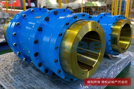
Gear Coupling Is More Reliable For Continuous PU Sandwich Panel Manufacturing Line
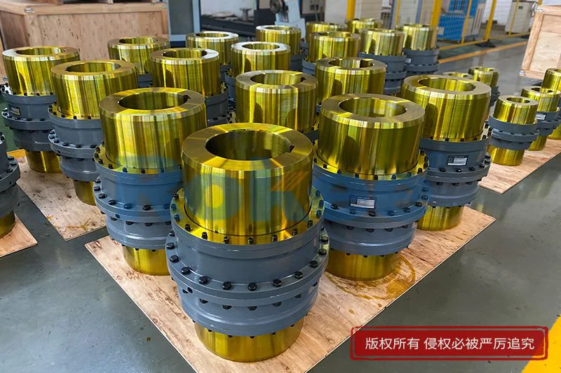
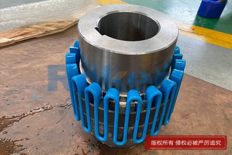
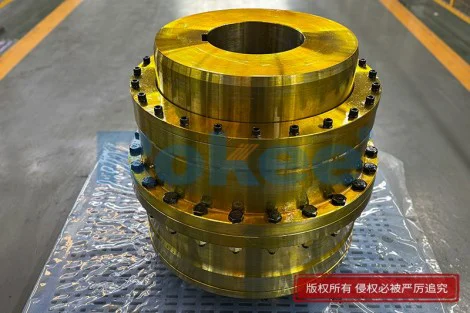
A continuous polyurethane sandwich panel manufacturing line represents one of the most demanding environments in modern panel production, where raw materials such as facings, polyurethane chemicals, and insulating cores move through a single uninterrupted sequence from unwinding to cut-to-length stacking. The line depends on a tightly synchronized chain of drive units, each connected through couplings that link electric motors, gear reducers, conveyor rollers, pressure belts, and side sealing systems. Within this chain, the coupling acts as a mechanical translator: it must rotate without play while also absorbing the small but inevitable offsets between shafts, and it must do so hour after hour across shifts that rarely stop once the production recipe has been established. Any coupling failure immediately disrupts the continuous flow, leaving half-cured panels trapped between belts, wasting chemical batches, and forcing maintenance crews to intervene under time pressure. Among the coupling options available to line designers and operators, the gear coupling has consistently proven itself as the most reliable choice for this specific duty. Its design is based on precision-machined metallic teeth that mesh between a hub on one shaft and an outer sleeve on the other, allowing angular and parallel misalignment while transmitting torque through a large contact surface. Unlike flexible elements that depend on elastomer deformation, the gear coupling relies on controlled sliding between lubricated tooth flanks, a principle that has been refined over decades of heavy industrial drive applications. This fundamental difference in working physics explains why gear couplings continue to dominate in long, heavily loaded, continuously running production lines where even a brief unplanned stop can erase the profit margin of an entire shift.
To understand why gear couplings suit continuous PU sandwich panel lines, it helps to examine exactly what the coupling must tolerate during a normal production campaign. A polyurethane sandwich panel line typically combines a top and bottom metal facing, injects or pours reacting chemical components between them, and carries the assembly through a heated double-band conveyor where the foam rises, cures, and bonds to both facings. The conveyor bands and their supporting rollers are driven by several motor-reducer units distributed along the length of the line, and each of these units must run at a carefully matched peripheral speed. Over a campaign of several hours, the line is exposed to subtle mechanical disturbances: the foundation settles slightly as heavy sections heat up, the steel frame expands non-uniformly under the influence of heated conveyor zones, bearing housings wear marginally, and the belt itself imposes varying radial loads on rollers. A rigid coupling would transmit these misalignments directly into bearings and seals, causing rapid fatigue and premature failure. A gear coupling, by contrast, is engineered so that the crowned or slightly curved teeth on the hub can slide within the internally toothed sleeve, accommodating angular offsets of a fraction of a degree and parallel offsets measured in millimeters without overloading the connected shafts. This sliding action, when properly lubricated, introduces only modest friction and generates heat slowly, and the tooth geometry is designed so that torque is shared across multiple teeth rather than concentrated on a flexible element that can fatigue. The result is a coupling that remains dimensionally stable under the very thermal and mechanical conditions that would cause softer alternatives to creep, soften, or crack within a few weeks of continuous operation.
Misalignment is not the only challenge; the coupling must also transmit torque that changes in character as the production recipe progresses. At the moment the chemical components react and foam begins to rise, the resistance to movement inside the conveyor can rise sharply, placing a brief but heavy torsional demand on the drive that pulls the facing and the band through the curing section. Later, when the foam has cured and the panel moves freely, the torque returns to a relatively steady level. A coupling that relies on rubber elements may see these transient torque spikes as repeated shocks that accumulate damage over time, creating internal cracks that propagate until the element fails without warning. A gear coupling, with its full metal-to-metal torque path, experiences these spikes as short periods of increased sliding between tooth flanks rather than as destructive flexing. The contact area of the teeth distributes the load, and the lubricating film between the flanks absorbs the initial shock before it can hammer the surface. This behavior is particularly valuable on PU lines because the exothermic nature of polyurethane reaction means that torque variations are not merely occasional but inherent to the process itself. Operators who have run lines fitted with elastomeric couplings often describe the pattern as a predictable cycle: the coupling element degrades slowly for months, then suddenly fails during a foam-rise event, leaving a length of half-bonded panel stranded in the cure tunnel. Gear couplings, when correctly sized and lubricated, rarely produce this kind of catastrophic failure; instead, their wear shows up as gradually increasing backlash, which can be detected during routine inspections and addressed during a planned changeover. The difference between unexpected destruction and gradual, measurable wear is the difference between a production line that responds to maintenance on its own schedule and one that is dictated by failures.
Thermal behavior is another dimension where gear couplings demonstrate their superiority in continuous PU panel manufacturing. A typical line runs for long stretches at elevated ambient temperatures because the curing section deliberately heats the foam to accelerate reaction. Heat rises from the band and supporting structure, and the coupling at the output of each reducer sits in an environment where surrounding air can be significantly warmer than normal shop conditions. Elastomeric elements, however well compounded, lose their modulus as temperature rises; a coupling that feels stiff and reliable on a cool morning can become soft and prone to slip under the same torque by mid-afternoon as the line reaches steady-state temperature. Over repeated heat cycles, the rubber takes on a permanent set, hardens, and eventually develops surface cracks that allow small misalignment motions to become large relative motions. Gear couplings have no polymer in their torque path, so their dimensional stability is governed primarily by the lubricant and by the thermal expansion of steel, which is predictable and consistent. A properly sealed gear coupling retains its lubricant across the full operating temperature range, and the sliding teeth generate a modest amount of friction heat that is conducted away through the metal sleeve and shaft. Because steel does not suffer the time-dependent softening that plagues rubber, the coupling continues to transmit the same torque with the same angular stiffness after months of operation as it did when newly installed. This thermal indifference is especially valuable on lines that run through seasons or through product changes that require different cure temperatures; the coupling does not need to be re-selected or derated when the cure recipe changes, and maintenance crews do not need to carry spares of different hardness ratings. The reliability that operators value is not simply that the coupling works on day one, but that it works in the same way on day three hundred of continuous running.
Maintenance considerations further reinforce the case for gear couplings on continuous PU sandwich panel lines. Production lines of this type are typically scheduled around a few controlled changeovers per week, during which operators clean nozzles, inspect belts, and prepare the next facing coil. Any coupling that can be inspected and serviced within this window contributes directly to output, while any coupling that requires disassembly of major drive components or long cooldown periods becomes a source of lost production. Gear couplings are built around a relatively simple inspection: once the outer cover is removed, the condition of the tooth mesh and the lubricant can be assessed visually, and the sleeve can be replaced or regreased without removing the reducer or the roller from its mounting. This modular design means that planned maintenance is measured in tens of minutes rather than hours, and that the coupling can be kept in a known-good state throughout the campaign. In contrast, couplings that depend on flexible discs or elastomeric spiders often require precise re-alignment after every element replacement, because removing the element changes the shaft position slightly; the time spent re-aligning, checking dial indicators, and re-torquing fasteners can easily consume an entire shift window. Gear couplings tolerate this procedure much more forgivingly because their tooth geometry absorbs the small positional changes that occur when the sleeve is replaced. Additionally, because the wear rate of gear couplings is well understood and depends on load, misalignment, and lubricant condition, maintenance planners can estimate service life with reasonable confidence and schedule sleeve replacements at times when the line would otherwise be idle. This predictive reliability transforms maintenance from a crisis response into a controlled activity, and in continuous production industries that transformation is often worth more than the purchase price of the coupling itself.
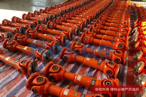
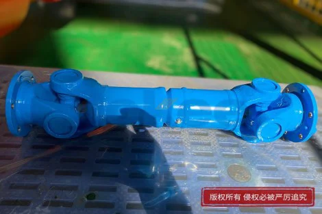
A direct comparison with other common coupling types helps to isolate why gear couplings remain preferred on PU sandwich panel lines. Jaw-type couplings, which transmit torque through an elastomeric spider sandwiched between two metallic hubs, are inexpensive and easy to install, but they are limited in torque capacity for their size and are sensitive to the same heat and chemical atmosphere found near the foam injection zone. The spider is the wearing component, and when it fails it does so suddenly, often leaving one shaft disconnected while the other coasts, which can damage facing winding or cause belt mis-tracking. Disc couplings, which use stacks of thin stainless steel discs to transmit torque while allowing angular and parallel motion, are precise and torsionally stiff, but they are expensive, sensitive to point loading from improper installation, and prone to disc fatigue when exposed to repeated torque spikes from the foam-rise event. Chain couplings, where a roller chain spans two sprockets, are compact and tolerate misalignment, but the chain wears quickly in continuous high-speed service and requires frequent lubrication that can attract dust and chemical overspray in the panel line environment. Universal joints, while excellent at accommodating large angles, introduce small fluctuations in angular velocity at each rotation that, over many cycles, can encourage belt slip and uneven panel speed. Gear couplings occupy a middle ground that matches the PU line duty cycle well: they are torsionally rigid enough to preserve synchronous speed between drive sections, flexible enough to absorb the misalignment that long steel frames develop, robust enough to survive torque spikes, and sealed against the chemical and dust-laden atmosphere typical of foam production. This combination of properties is difficult to find in any single alternative, and it is the reason engineers returning to specify lines year after year continue to choose gear couplings for the main conveyor drives.
Materials and surface engineering play a quiet but decisive role in the reliability of gear couplings in this application. The hubs and sleeves are typically machined from alloy steels that are then case-hardened on the tooth flanks, producing a hard wear-resistant surface over a tough, ductile core. This combination is essential because the teeth must slide against each other under load without galling, yet they must also absorb occasional shock loads without chipping. The tooth profile itself is often modified: teeth on the hub are crowned slightly along their length, and the sleeve teeth may be relieved at the ends, so that contact is concentrated in the middle of the flank rather than at the edges where stress concentrates under misalignment. This geometric tuning means that even when the shafts are offset by a few millimeters, the load is distributed across the working face rather than hammered onto a corner of the tooth. Surface treatments such as phosphate or manganese coating provide a reservoir for lubricant and protect against initial wear during run-in, while the lubricant chosen for the coupling is formulated to withstand the high temperatures and to resist being washed away by any cleaning fluids used around the line. Internal seals, often lip seals or O-rings retained between the sleeve and cover, keep the lubricant in and prevent dust, chemical overspray, and fine foam particles from entering the mesh. Even small improvements in these details matter on a continuous line: a worn seal allows contamination that accelerates tooth wear by an order of magnitude, while a properly sealed coupling can run for years on a single charge of grease. The cumulative effect of these material and geometric choices is a coupling whose wear rate is slow, predictable, and visible, rather than one that fails abruptly when a hidden internal element reaches its fatigue limit.
Integration with the rest of the drive train is another reason gear couplings fit naturally into continuous PU sandwich panel lines. Each drive section consists of an electric motor coupled to a gear reducer, and the reducer output shaft connected through a coupling to the conveyor roller or to the band drive drum. Because the line must maintain nearly identical surface speeds across several independent drive units, any coupling that introduces torsional windup or speed variation can create tension fluctuations in the facing material and in the steel band. Gear couplings, with their metal-to-metal tooth contact, have essentially zero torsional windup under normal load, so the speed relationship between the reducer and the roller is rigidly preserved. This is particularly important when the line is stopped for a short time and then restarted: a coupling with windup can store energy during the stop and release it unevenly on restart, causing the band to jerk and possibly damaging the half-cured panel. The gear coupling transmits the restart torque immediately and smoothly, allowing the drive control system to bring the line back to speed without oscillation. Furthermore, because gear couplings can be designed with a limited end float feature, they can accommodate the axial movement that rollers experience as they expand under heat, without forcing the roller to push against the reducer bearing. This axial freedom is built into the coupling rather than into the drive train, which keeps bearing loads within design limits and avoids the premature failures that arise when rollers are forced to push or pull on fixed-shaft reducers. Across a long line with many drive points, this careful division of mechanical functions—torque transmission, misalignment absorption, and axial float compensation—within a single robust component is an engineering solution that reduces the number of interfaces and therefore the number of potential failure points. Operators recognize this intuitively: every additional flexible element between motor and belt is another thing that can wear out, and the gear coupling's ability to combine several functions in one unit directly reduces the total number of spares and inspections the maintenance team must manage.
Beyond mechanical performance, the economic logic of using gear couplings on continuous PU sandwich panel line rests on the cost of unplanned downtime. A PU line running at a typical production speed turns out many square meters of panel per minute, and each minute of stopped production represents not only lost output but also wasted chemical raw material left in the mixing system, half-cured product trapped in the cure tunnel, and labor devoted to cleaning the belts and facings before restart. When a coupling fails, the time required to source a replacement element, align the shafts, and restart can run into hours, and during that time the line is not earning revenue. Gear couplings, because they wear gradually and because spare sleeves are commonly kept on site, shorten the recovery window dramatically; a maintenance team that notices increasing backlash during an inspection can schedule a sleeve change during a planned changeover, absorbing the cost in time that would otherwise be spent cleaning or preparing the next facing. Over months and years, this predictable wear behavior translates into steadier output, less overtime for maintenance crews, and more consistent product quality, because the line speed and tension profile remain stable rather than fluctuating as flexible elements degrade. Plant managers who have operated lines with different coupling philosophies often describe the gear-equipped line as the one they stop worrying about: once it is running at the start of a campaign, the coupling does not feature in the daily list of concerns, and attention can be directed toward chemical ratios, facing quality, and finished panel appearance. This psychological reliability, the confidence that the mechanical drive will not surprise the operators, is itself a form of productivity, because it allows the team to focus on the variables that actually determine product quality rather than on the ones that could cause an unplanned stop. In an industry where the margin on each panel is modest and depends on high line utilization, that confidence is a genuine competitive advantage.
In summary, the choice of gear coupling for a continuous polyurethane sandwich panel line is not a matter of tradition alone; it follows directly from the combination of demands that this production environment places on every mechanical interface. The line runs continuously for long periods, distributes drive torque across several units along its length, operates at elevated temperatures, experiences torque spikes as the foam reacts, and must absorb the small but persistent misalignment that arises from long steel frames, thermal expansion, and bearing wear. Gear couplings meet these demands because they transmit torque through a large, lubricated, metal-to-metal tooth surface, accommodate misalignment without relying on polymer deformation, retain their dimensional stability across heat cycles, wear in a gradual and inspectable way, and can be serviced within the normal changeover window without repeated precision realignment. Alternatives may be cheaper to purchase or easier to install, but they introduce failure modes—sudden elastomer rupture, disc fatigue, chain wear, or thermal softening—that are poorly matched to the continuous, heat-intensive, chemical-laden environment of a PU panel line. When these failure modes occur, they do not merely stop a motor; they strand half-cured panels, waste costly chemical batches, and erode the utilization that the line was designed to deliver. By contrast, a well-specified, well-lubricated gear coupling behaves predictably across months of operation, and its gradual wear can be planned for rather than reacted against. For operators whose business depends on keeping the line moving, on producing panels of consistent quality, and on protecting the investment in raw material and labor, the gear coupling remains the most reliable mechanical link in the drive train, and its continued preference in this demanding application reflects the simple reality that in continuous manufacturing, the most dependable component is the one that can be forgotten until the next planned inspection.