Gear Coupling Cooperates With Continuous PU Sandwich Panel Line To Improve Production Efficiency
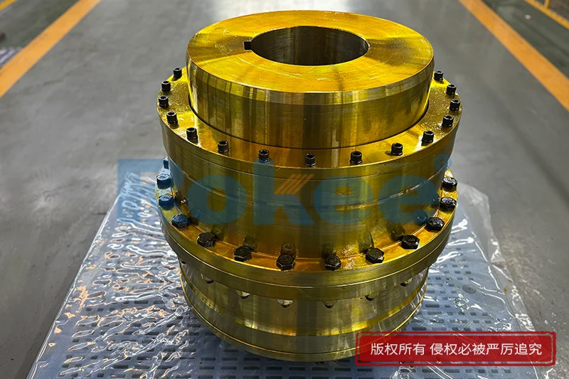
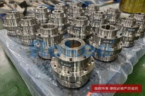
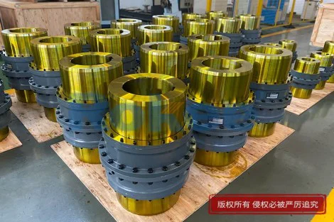
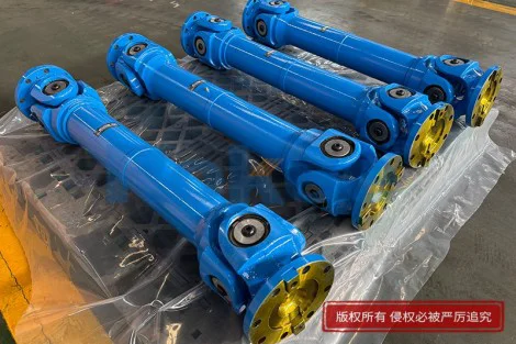
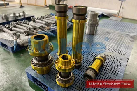
The continuous PU sandwich panel line represents one of the most demanding material-processing environments in modern manufacturing, where every rotating shaft, drive roller, and conveyor chain must move in precise synchronization from the moment foam is injected onto the bottom facing until the finished panel exits the cutting saw. At the heart of this mechanical orchestra sits a relatively unassuming but absolutely critical component: the gear coupling. Unlike simple elastomeric sleeves or rigid flanged connections, a gear coupling is engineered to transmit extremely high torque between two shafts while simultaneously accommodating the angular, parallel, and axial misalignments that inevitably arise as machines warm up, beds flex under load, and foundations settle over years of operation. In a continuous panel line, where a single roller drifting out of alignment by a fraction of a millimeter can cause the facing to wrinkle, the foam core to delaminate, or the cutting length to fall out of tolerance, the quality of the coupling directly determines whether the line runs at design speed or crawls along at half capacity with constant manual intervention. Understanding how a well-matched gear coupling cooperates with the rest of the line—how it absorbs shock loads from the extruder, compensates for thermal growth in the curing oven, and protects the reducer from reactive forces in the cut-off saw—is therefore essential for any production manager chasing higher output, lower scrap rates, and longer mechanical service life. This article walks through that cooperation in detail, paragraph by paragraph, from the first principles of torque transmission all the way through to the maintenance practices that keep the partnership productive year after year.
To appreciate why a gear coupling is chosen over other coupling types on a continuous PU sandwich panel line, it helps to first understand the loads the line actually imposes. A typical continuous line consists of an uncoiler for the bottom steel or aluminum facing, a preheating station, a foam mixing head that pours the two-component polyurethane mixture onto the moving facing, a top facing laminating station, a long curing oven where the foam expands and cures between the two facings, a profiling and embossing section, a traveling cut-off saw that slices the moving panel to length, an output conveyor, and a stacking system. Each of these stations contains rollers, sprockets, conveyor belts, or knives driven by electric motors through gearboxes. The torque demands are not steady: the mixing head pulses as it dispenses chemicals, the oven rollers see expanding foam pushing against them, the saw carriage accelerates and decelerates repeatedly, and the stacker drops panels with mechanical impact. A rigid coupling would transmit every one of these shocks directly into the reducer bearings and motor shafts, causing rapid wear and catastrophic failure. An elastomeric coupling can handle misalignment but often lacks the torque density and durability needed for the heaviest driven rollers. The gear coupling, with its curved or straight internal teeth meshing with external teeth on the mating hubs, sits in a sweet spot: it transmits torque through metal-on-metal tooth contact with essentially zero backlash when properly designed, allows angular misalignment of up to a degree or more per tooth set, and tolerates axial sliding as shafts expand thermally. This combination of high torque capacity, compact envelope, and measurable misalignment compensation is why gear couplings are found on the main drive spindles, the oven chain drives, and the heavy conveyor rollers of nearly every high-speed continuous PU line in operation today.
The first place the gear coupling proves its worth is at the main drive that pulls the entire sandwich panel through the line. This puller drive is often the bottleneck that sets the maximum line speed: if it cannot pull steadily without slipping or jerking, the foam density across the panel becomes uneven, the facing stretches, and the cut-to-length accuracy degrades. The main drive motor spins at a high speed but relatively low torque, so it is coupled through a gear reducer that steps the speed down and multiplies the torque. Between the motor and the reducer, and again between the reducer output shaft and the puller drum or chain, sits a gear coupling. The first coupling handles the high-speed, lower-torque side; the second handles the low-speed, very high-torque side where the actual pulling force is generated. Because the two shafts—motor shaft and reducer input shaft, reducer output shaft and puller drum—are never perfectly coaxial in practice, the gear coupling's tooth set allows a small angular error and a small parallel offset without binding. When the line starts up from a dead stop, the coupling also dampens the torsional shock: the teeth can rotate microscopically under the elastic oil film that separates them, absorbing the torque spike that would otherwise hammer the gearbox. Over months of running, this shock absorption translates into measurable benefits: reducer oil stays cleaner because bearings are not spalling, keyways do not loosen, and the coupling itself does not develop fretting corrosion at the hub interfaces. The result is a puller that holds a constant line speed even when the foam viscosity changes between product runs, which is the single most important factor for consistent panel quality and maximum throughput.
Moving downstream into the curing oven, the gear coupling faces a very different challenge: heat. The oven chamber runs at elevated temperatures for long periods, and the rollers that carry the panel through the oven expand thermally along their axes. A rigid shaft connection would bind as the roller elongates, exerting enormous axial force on the bearings and eventually seizing them. The gear coupling is designed precisely for this: the sleeve can slide axially along the teeth of the hub as the shaft grows, turning what would have been a destructive binding force into a harmless sliding motion. At the same time, the high ambient temperature inside the oven area means the coupling's lubricant must remain stable. Gear couplings used on oven rollers are typically packed with a high-temperature, extreme-pressure grease or oil that does not thin out and run away, nor thicken and fail to lubricate at startup. The tooth surfaces are usually phosphate-coated or plated to resist corrosion from the humid, chemically active oven atmosphere, where polyurethane fumes and condensation are present. When the coupling is correctly specified for the oven environment, the rollers turn freely at a constant speed throughout a multi-hour production run, the panel cures evenly, and the line can stay at its target speed rather than being slowed down because an oven roller is dragging. Production efficiency gains here are not dramatic in a single shift, but they compound: a line that can run at full oven speed for three shifts a day, five days a week, will produce significantly more finished panels per month than one that must be throttled back because of overheating or seized couplings. The coupling, in other words, is silently enabling the oven to do its job.
Another critical cooperation point is the cut-off saw, which is arguably the most mechanically violent station on the entire line. The saw blade must slice through a moving sandwich panel—steel facing on both sides with a rigid PU core—in a single pass while the saw carriage travels along the panel at exactly the same line speed. Any speed mismatch causes the blade to bind, burn, or tear the facing, and any reactive torque kicked back through the carriage drive can damage the precision ballscrew or rack-and-pinion that positions the cut. The gear coupling between the carriage motor and the carriage drive, and between the spindle motor and the saw blade arbor, acts as a mechanical shock absorber during the cut. When the first tooth of the saw bites into the steel facing, the reaction torque spikes momentarily; the gear coupling's tooth mesh, cushioned by its lubricating film, absorbs that spike instead of transmitting it directly into the gearbox or the arbor bearings. This protection matters because the saw spindle spins at several thousand revolutions per minute, and even tiny amounts of backlash or misalignment at that speed translate into vibration, blade wobble, and poor cut quality. A high-quality gear coupling with a close-fitting tooth profile, properly pre-lubricated, and aligned during installation keeps the arbor true, the cut square, and the blade life long. When the saw cuts cleanly every time, the panel does not need to be trimmed or scrapped, the line does not have to stop to change a dulled blade, and the cut length remains within tight tolerance. Multiply that by hundreds of cuts per shift and the efficiency contribution is substantial.
Beyond the individual stations, the gear coupling plays a coordinating role in the line's overall synchronization. A continuous PU sandwich panel line is, in effect, a very long conveyor where the speed at every point must match exactly: the bottom uncoiler must feed facing at the same speed as the puller, the top uncoiler must match as well, the oven rollers must not drag or push, and the output stacker must receive panels at the same rate they are cut. Any coupling that introduces backlash, slip, or torsional wind-up into a driven roller creates a speed error that propagates through the line. The gear coupling's metal-to-metal tooth mesh, when new and correctly preloaded, has essentially zero rotational backlash, which means the driven roller follows the reducer's output shaft exactly. This rigidity is what allows the line to be driven by a single centralized speed reference—often drawn from the main puller—and have every downstream station track that reference within a few millimeters per minute. When operators change the line speed for a different product thickness, the couplings transmit the new speed immediately and without lag, so the foam pour rate, the oven dwell time, and the cut length all stay in proportion. Without this stiff, precise torque transmission, the line would require independent closed-loop control on every roller, which adds cost, complexity, and failure points. The gear coupling, by doing its mechanical job simply and reliably, allows the line's control system to be straightforward and robust—and that simplicity is itself an efficiency driver.
The efficiency story is not only about running faster; it is also about running longer between stops. Every time a continuous line is stopped and restarted, several things happen: the foam already poured but not yet cured may be wasted, the oven must re-stabilize at temperature, the facing rolls must be re-threaded, and the cut-off saw must re-home. Depending on the length of the stop, these losses can cost tens of minutes of production and several kilograms of raw material. A large share of unplanned stops on PU lines traces back to mechanical transmission failures, and a significant fraction of those transmission failures trace back to couplings: worn tooth sets, failed seals that let grease escape, hubs that slipped on their shafts because the keyway was not properly fitted, or couplings that were misaligned during installation and overheated. A properly selected, installed, and maintained gear coupling avoids all of these failure modes. Its metallic tooth design does not fatigue the way elastomeric elements do under repeated shock, its sealed design keeps contaminants out, and its robust hub fit does not loosen over time. The result is a mean time between failures that is measured in years rather than months, and a line that spends more of its calendar time actually producing panels. When production planners look at equipment effectiveness, the distinction between a line that runs at 85 percent availability and one that runs at 95 percent is the difference between meeting monthly targets and falling behind—and a large part of that gap is locked up in small, often overlooked components like the gear coupling.
Installation and alignment are where the theoretical cooperation becomes practical, and they are also where many lines lose efficiency before they ever start producing at full speed. Gear couplings look simple, but they are precise mechanical instruments: the two hubs must be mounted on their shafts with proper interference or keyed fit, the sleeve must slide freely over the teeth, and the two shafts must be aligned within the manufacturer's tolerance for angular and parallel offset. If alignment is sloppy, the coupling does not rotate freely; instead, the teeth bind at certain points in every revolution, creating a periodic pulsation in the torque. That pulsation shows up downstream as a subtle speed oscillation in the driven roller, which translates into uneven foam density, slight facing wrinkling, or cut-length variation. Worse, the binding accelerates wear on the teeth, shortens coupling life, and can transmit damaging loads into the bearings. Conversely, when alignment is done carefully with a dial indicator or laser alignment tool, and when the coupling is given the correct axial freedom to slide, it spins with almost no effort, runs cool, and transmits torque smoothly. Experienced line installers know that spending an extra half day aligning every gear coupling on a new line pays for itself many times over in the first year of operation, in the form of lower energy consumption (a misaligned coupling draws more current for the same output), smoother panel quality, and longer coupling life. This is not glamorous work, but it is one of the highest-return efficiency investments available.
Maintenance is the third leg of the stool, alongside correct specification and correct installation. A gear coupling is not a set-it-and-forget-it component; it lives or dies on its lubrication. The tooth mesh relies on a continuous film of grease or oil to separate the tooth surfaces and prevent metal-to-metal contact. Over time, even in a sealed coupling, the lubricant breaks down from heat, oxidation, and shear. Water ingress, especially in the humid environment around the foam mixing and curing sections, accelerates this degradation. A well-run line will have a scheduled lubrication program: gear couplings are inspected at planned intervals, their seals are checked for leaks, and the grease is replaced or replenished according to a fixed interval tied to operating hours rather than calendar time. During these inspections, the maintenance team can also measure the gap between hubs to detect axial movement, check for unusual play that indicates tooth wear, and look at the coupling bore and keyway for signs of fretting. When a coupling shows wear, it is replaced before it fails—during a planned maintenance window rather than in the middle of a production run. This preventive approach means the line can be scheduled for downtime at convenient times, minimizing lost production. The alternative, waiting for a coupling to strip its teeth at two in the morning on a Saturday, is not just expensive in parts and labor; it is expensive in the missed production window, the scrap panels, and the overtime required to catch up. The gear coupling, because it is a wearing part with predictable service life, turns out to be one of the easiest components on the line to manage proactively—and that predictability is a quiet but important contributor to overall plant efficiency.
The economic logic of choosing and caring for gear couplings on a continuous PU sandwich panel line is ultimately an exercise in leverage. The coupling itself is a modestly priced component relative to the motor, the reducer, the oven, or the saw. But because it sits at the junction between rotating power and driven load, every percentage point of improvement in its performance ripples outward: the puller holds speed more steadily, the oven rollers do not drag, the saw cuts cleaner, the line runs longer between stops, and the finished panels come out with tighter dimensional consistency. The scrap rate drops, the energy consumption per panel falls, and the maintenance budget shifts from emergency repairs to scheduled inspections. When several gear couplings across the line are all performing well together, the cumulative effect is a line that can run at its design speed for most of its operating hours, rather than being held back by one weak link. Operators and maintenance crews who understand this relationship tend to treat the couplings not as spare parts on a shelf but as precision instruments that deserve correct sizing, careful alignment, and disciplined lubrication. The result is a production system in which the gear coupling cooperates silently but decisively with every other station, turning raw coils of facing and liquid polyurethane into finished panels at a rate that makes the entire investment worthwhile. In the end, improving production efficiency on a continuous PU sandwich panel line is rarely about one big dramatic change; it is about getting hundreds of small mechanical details right, and the gear coupling is one of the smallest yet most consequential of those details.