Operation And Maintenance Guide For Continuous PU Sandwich Panel Line With Universal Shaft to Extend Equipment Life
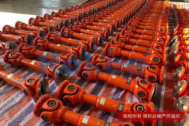
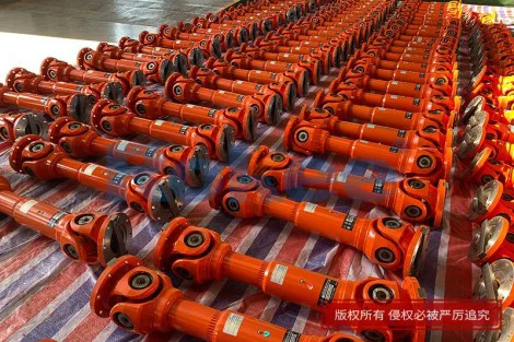
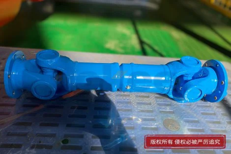
A continuous PU sandwich panel line represents one of the most sophisticated integrated manufacturing systems in the building envelope industry, combining unwinding, pre-painting, edge profiling, foam metering, laminating, curing, cutting, and stacking into a single synchronized flow. At the heart of this flow sit the universal shaft drive assemblies that transfer torque from the main gearboxes to the conveyor chains, the face sheet feeding rollers, and the multi-section laminating press. Unlike rigid couplings, universal shafts accommodate angular misalignment, axial displacement, and minor parallel offset between the driving and driven shafts, which is essential because a long production line naturally experiences thermal expansion, foundation settlement, and dynamic load variation across its thirty to sixty meter length. When these shafts are neglected, the consequences propagate quickly: uneven panel density, wrinkled face sheets, premature chain wear, vibration-induced bearing failure, and eventually unplanned shutdowns that can erase an entire shift of output. Extending equipment life therefore begins with understanding that the universal shaft is not a passive connector but a precision transmission component whose condition directly governs line speed, product consistency, and mechanical reliability. Operators and maintenance crews who treat the shaft as a black box tend to discover problems only after a catastrophic failure, whereas those who monitor its temperature, vibration, play, and lubrication state can predict and prevent issues weeks in advance. The following guide is organized around the practical disciplines that keep such a line running smoothly over years rather than months, starting with the operating philosophy and moving through installation, daily care, lubrication, alignment, wear inspection, load management, troubleshooting, record keeping, and long-term life extension strategy.
The first operating principle for any continuous PU sandwich panel line is that the universal shaft system must never be subjected to shock loading or torsional reversal. PU foam chemistry demands a steady conveyor speed so that the reacting isocyanate and polyol mixture has a consistent dwell time in the curing tunnel; a sudden jerk from a slipping coupling or a binding universal joint creates a speed ripple that shows up as density variation across the panel width. Operators should ramp the main drive up and down gradually, using the inverter's acceleration and deceleration parameters rather than switching the line on and off at full speed. When changing panel thickness, the laminating press opening should be adjusted only while the line is running at a slow crawl, never while stationary under full hydraulic pressure, because a locked press followed by a sudden start imposes a torque spike that can bend the universal shaft tube or crack the yoke welds. Similarly, the line should be stopped in a controlled sequence: first stop the foam metering, then flush the mixing head, then reduce conveyor speed to zero, and only then cut the main drive power. Abrupt emergency stops are sometimes unavoidable, but every such event should be logged and followed by a visual inspection of the universal shafts, because a single hard stop can introduce microscopic fatigue cracks that propagate over the following weeks. Operators should also avoid running the line at speeds below the manufacturer's recommended minimum for extended periods, since very slow rotation causes the needle bearings inside the universal joints to skid rather than roll, producing brinelling and false brinelling marks that accelerate wear. The discipline of smooth starts, controlled stops, and steady speed is the cheapest and most effective life-extension measure available, requiring no spare parts and no additional budget, only attentiveness and consistent procedure.
Proper installation and initial alignment of the universal shaft assemblies lay the foundation for everything that follows. Each shaft has a rated operating angle, typically limited to a few degrees per joint, and exceeding this angle dramatically shortens needle bearing life because the bearing load distribution becomes uneven. During installation, the driving and driven flanges should be brought as close to collinear as possible, with the universal shaft resting horizontally or at a gentle slope that matches the natural geometry of the line. The shaft should never be forced into position with a pry bar; if the flanges do not meet, the gearbox or the driven roller should be re-shimmed rather than the shaft bent or hammered. When bolting the flanges, the bolts should be tightened in a diagonal sequence to a torque value appropriate for the bolt grade and diameter, and lock washers or thread-locking compound should be used to prevent loosening under vibration. After installation, the shaft should be rotated by hand through at least two full revolutions to confirm that it turns freely without any tight spot or rubbing against guards. During commissioning, a short trial run at low speed should be observed from a safe distance, listening for irregular clicking, knocking, or high-pitched whirring that indicates misaligned bearing cups or insufficient preload. It is also important to verify that the shaft's axial travel is not constrained by end caps or that its telescopic spline section is not bottoming out as the line heats up; a universal shaft needs a small amount of free axial movement to absorb thermal expansion, and pinning it rigidly at both ends creates bending stress that the joints were never designed to carry. Taking the time to align correctly on day one pays back many times over during the following years of operation.
Daily and weekly maintenance routines should be built around simple observations that any trained operator can perform without special instruments. At the start of each shift, before the line reaches full operating speed, the crew should walk the length of the machine and visually inspect each universal shaft for signs of oil leakage, cracked rubber boots, bent tubes, and loose flange bolts. A smear of fresh grease around a joint may indicate a failed seal, which allows both lubricant loss and contaminant ingress. During the first few minutes of running, an infrared temperature scan of each universal joint can reveal overheating bearings; a joint that runs noticeably hotter than its neighbors, or that is too hot to touch, should be scheduled for inspection before the next production run. Vibration should also be felt and heard: a healthy universal shaft transmits a smooth, low hum, while a worn joint produces a rhythmic vibration at twice the rotational frequency, caused by the velocity fluctuation inherent to single universal joints. The conveyor chain tension, the face sheet roller pressure, and the laminating press height should all be checked because an over-tight chain or a misadjusted roller adds side load to the driven shaft, which the universal joint must absorb through its bearing needles. Every week, the guards should be opened and the telescopic spline sections of the longer shafts checked for freedom of movement; if a spline is rusted or packed with dried foam residue, it will not slide, and the resulting axial stress will tear the joint yokes. Cleaning should be done with a soft brush and a non-corrosive solvent, never with a high-pressure jet aimed directly at the joint seals, because the jet can push water past the boot and into the bearing cavity. These short, recurring tasks take less than half an hour per shift but catch problems while they are still cheap to fix.
Lubrication is the single most important controllable factor in universal shaft longevity, and on a PU sandwich panel line it is complicated by the presence of polyurethane overspray, isocyanate fumes, metal dust from profiling, and occasional moisture from condensing water on cold rollers. The needle bearings inside each universal joint and the splines of each telescopic section require a lubricating grease with good extreme-pressure properties, strong adhesive tenacity, and resistance to water washout. The grease nipples should be accessed while the shaft is at rest and rotated to a position where all fittings are reachable; grease should be pumped in slowly until fresh grease emerges from the relief point or the seal lip, which confirms that old contaminated grease has been purged. Over-greasing is a real risk because it can blow out the joint seals, so a few slow pumps are better than one continuous burst. The lubrication interval depends on operating hours and ambient conditions, but as a general practice each fitting should receive attention on a scheduled basis rather than when a problem appears. The spline section, which often slides inside a protective sleeve, should be wiped clean and then lightly re-greased with a high-molybdenum grease that resists fretting corrosion. It is essential to use the same grease type consistently, because mixing lithium-based and calcium-based greases can cause the soap structure to break down and liquefy. Storage of grease cartridges should be clean and dry, with the nozzle capped to prevent PU dust from being injected into the joint along with the fresh lubricant. A written lubrication chart posted near each shaft group, marked off after each service, prevents both missed fittings and redundant over-lubrication.
Alignment verification should not stop at installation; it should be rechecked on a periodic basis, especially after foundation work, after a major component replacement, or after any event that introduces new vibration. A simple straightedge across the two flanges, combined with feeler gauges, can reveal horizontal and vertical offset, while a dial indicator mounted on one flange and rotated against the other can measure runout. On long lines, the thermal growth of the steel frame between the morning cold start and the afternoon steady-state temperature can be several millimeters, and the universal shafts are expected to absorb this movement through their angles and splines. If a shaft has been fitted with a rigid flange coupling on one end to "fix" a vibration problem, the underlying misalignment has simply been transferred to another bearing, and the fix should be undone so the universal joint can do its designed job. Operators should also watch the condition of the face sheet feed rollers, because a worn roller bearing creates a radial load that the universal shaft must compensate for, and replacing the roller bearing is far cheaper than replacing a universal joint. When realignment is needed, the shaft should be removed, inspected, and re-fitted rather than shimmed in place; a shimmed joint hides the true angular relationship and gives a false sense of alignment. Many premature universal shaft failures on PU lines are traceable not to defective parts but to gradual foundation settlement that was never corrected, allowing the operating angle to creep beyond its design limit year after year.
Wear inspection requires both visual and dimensional assessment, and it should be performed during planned maintenance windows rather than during a production run. When a universal shaft is removed, the needle bearings should be examined for pitting, spalling, blueing from heat, and brinelling indentations that match the number of needles around the race. The yoke bores where the bearing cups sit should show no elongation or score marks, and the cross trunnions should not exhibit any visible play when wiggled by hand. The spline teeth should be checked for wear on the pressure flanks; if the teeth show bright polishing on one side, it indicates a one-directional load that may point to a misaligned driven machine. The protective boots should be replaced at the first sign of cracking, because a split boot allows foam dust to enter and act like an abrasive paste against the needles. Any shaft that has been involved in a known overload event should be sent for magnetic particle or dye penetrant inspection, since fatigue cracks often start at the welds between the tube and the yokes and are invisible to the naked eye. Re-installation of a used shaft should only be considered after all tolerances have been measured and compared against the acceptable wear envelope; a shaft that passes visual inspection but has lost its needle preload will generate vibration that destroys neighboring bearings within weeks. Keeping a log of which shafts were removed, inspected, and returned to service allows the maintenance team to build a wear history and predict the replacement date before an in-line failure occurs.
Load management and operating discipline extend beyond the universal shaft itself to the way the whole PU line is run. The foam metering pumps, the laminating press hydraulic system, and the face sheet unwind tension all impose fluctuating torque on the main conveyor, and the universal shafts must transmit these fluctuations without shock. Operators should learn to read the line's behavior: if the foam head is delivering an inconsistent chemical ratio, the core density varies, the press load changes, and the drive torque swings, which appears at the universal joints as a series of micro-shocks. Correcting the chemical issue upstream protects the drivetrain downstream. Similarly, running the line at the highest possible speed for every product shortens life more than running at a moderate, stable speed, because higher centrifugal force throws grease off the needles and higher friction raises operating temperature. Product changes that require a different panel thickness should be treated as load transitions: the press opening is adjusted gradually, the speed is reduced during the changeover, and the universal shafts are visually checked after the new thickness has stabilized. Scrap panels should never be run backward through the line by reversing the conveyor, because the universal joint is not designed for sustained reversed rotation and the torsional reversal can dislodge needle rollers. The practice of "babying" the line through changes rather than forcing it through them is one of the cultural markers of a workshop that gets years of service from its transmission components.
Troubleshooting universal shaft problems on a running PU line follows a logical sequence that avoids both guesswork and unnecessary teardown. The first symptom is often an unfamiliar vibration or a periodic thump that coincides with the conveyor speed; the response is to identify which shaft group produces the noise by listening along the line and by feeling the tube temperature. If the vibration is rhythmic and doubles per revolution, suspect a worn universal joint or an imbalance in the rotating tube. If the vibration is accompanied by a grease leak, suspect a failed seal that has already contaminated the bearings, and plan replacement. If a shaft is hot but visually intact, suspect insufficient lubrication, a blocked grease line, or an operating angle that has grown too large due to settlement. If the line exhibits a periodic speed ripple that shows up as panel density bands, the cause may be a single universal joint whose inherent velocity variation is amplified because two adjacent joints are not correctly phased; universal joints in series should be phased so their angular accelerations cancel, and a re-phasing may be necessary after a shaft has been removed and replaced incorrectly. When a universal shaft fails in service, the line should be stopped immediately, because a broken joint can whip and damage guards, cables, and nearby operators; the failed shaft should be removed, the root cause documented, and a spare installed before restarting. Keeping at least one complete spare universal shaft of each critical size on site is a small capital expense that avoids multi-day emergency lead times and protects the production schedule.
The long-term extension of equipment life on a continuous PU sandwich panel production line is ultimately a documentation and culture project. Every universal shaft should carry an identification tag showing its installation date, its lubrication schedule, its last inspection, and any repairs it has undergone. Maintenance checklists should include specific universal shaft items rather than generic "drivetrain" entries, and shift handover notes should mention any unusual sound, temperature, or leak observed during the run. Operators should be trained to treat the universal shaft as a precision component, not a piece of steel bar, and should be encouraged to report small anomalies without fear of being overruled. Spare parts should be stored horizontally on racks, protected from dust and moisture, with the flange openings covered; a shaft stored vertically for years can develop spline fretting and seal deformation. Annual reviews of the maintenance records reveal wear patterns, reveal which positions fail most often, and guide decisions about upgrading to a slightly larger shaft size or improving the guarding. Over years of operation, a well-cared universal shaft system will outlast the gearboxes it serves, will require only periodic grease and boot replacement, and will silently enable the steady, high-quality production that makes a continuous PU sandwich panel line profitable. The investment of attention is small compared with the value it protects, and the habit of inspecting, lubricating, aligning, and recording becomes the strongest guarantee that the equipment delivers its full design life and beyond.