Grid Coupling With Cover
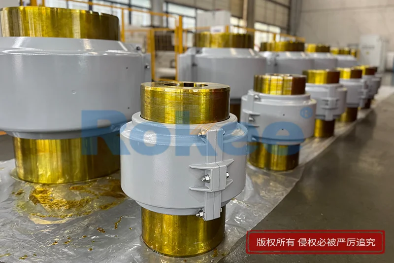
In the silent network of rotating machinery that underpins modern industry, the connection between a driving shaft and a driven shaft is rarely given the attention it deserves, yet it is precisely at this junction that a surprising amount of engineering effort is concentrated. A shaft coupling exists to transmit torque from one machine to another while tolerating the small but inevitable imperfections that exist between two independently mounted components. Among the many families of couplings available to the mechanical engineer, the grid coupling with cover occupies a distinctive middle ground: it is more flexible than a rigid sleeve, more robust than an elastomeric insert, and more forgiving of misalignment than many purely metallic alternatives. At its heart sits a serpentine, spring-like grid of hardened steel that bridges two toothed hubs, and around that grid sits a sealed, split cover that performs the quiet but essential jobs of retaining lubricant, deflecting flying debris, and shielding anyone who happens to pass nearby. This article explores what this device is, how it is built, why it behaves the way it does, and where it fits within the larger world of power transmission.
The story of how the grid coupling came to look the way it does is a story of gradual refinement rather than sudden invention. Early mechanical power transmission relied on long line shafts, leather belts, and rigid couplings that demanded extraordinarily precise alignment of every bearing and every machine bedplate. As electric motors and internal combustion engines became the preferred prime movers, and as machinery was increasingly mounted on separate foundations rather than on a common cast bed, the problem of shaft misalignment moved from being a rare and costly nuisance to being a daily reality that every coupling designer had to absorb. Pin-and-bush designs, jaw-and-insert designs, and chain couplings each emerged in response, but each carried its own compromise: rubber elements aged and crept, chains wore sprockets, and rigid components transmitted shock and vibration directly into bearings. The grid coupling answered by placing a thin, resilient steel grid — a wound spring in the shape of a long strip that bends alternately between gear teeth — between two hubs. That arrangement combined the high torque density of a steel torque path with the cushioned flexibility of a spring, and once it was found that the grid needed constant lubrication to survive, a cover naturally followed to hold the oil in and keep contamination out.
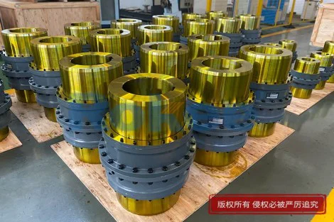
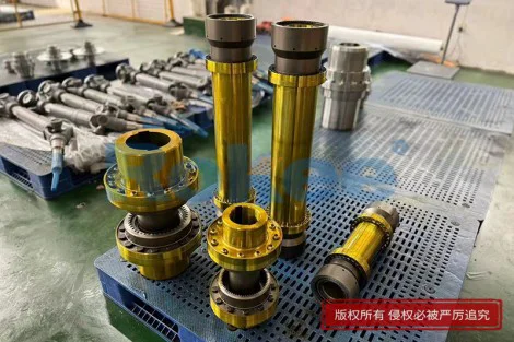
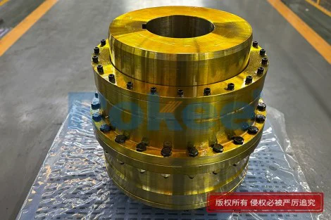
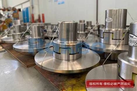
To understand a grid coupling with cover, it helps to take it apart in the mind before putting it back together in the machine. The assembly consists, at minimum, of two identical or near-identical flanged hubs, each bored to fit its respective shaft and keyed or interference-fitted in place. The outer face of each hub is machined with a row of curved, radially pitched teeth that wrap around the circumference, somewhat like the teeth of a fine gear but shaped with generous, rounded profiles rather than sharp involute flanks. Between the two hubs slides the grid itself: a strip of high-carbon, through-hardened steel wound into a serpentine or undulating path so that each crest of the grid engages the teeth on one hub and each trough engages the teeth on the other. The grid is split or looped depending on the exact arrangement, and it is slipped radially into the toothed cavities once both hubs are in position on their shafts. Over this entire sandwich sits a cover, usually in two bolted halves made of cast or stamped metal, lined with gaskets and fitted with seal rings at the bores where the hubs protrude. A fill plug, a drain plug, and sometimes a sight glass complete the assembly, turning the mechanical joint into a sealed, lubricated cartridge.
Torque flows through a grid coupling in a way that is both simple and subtly clever. When the driving hub turns, its teeth press against the engaged portions of the steel grid, and the grid in turn pushes against the teeth of the driven hub, dragging it along. Because the grid is not a rigid bar but a thin, springy strip running in a toothed channel, it does not transmit that push as a hard, instantaneous shove; instead, the engaged sections of the grid bend slightly as they deflect between the tooth gaps, and that bending stores and releases tiny amounts of elastic energy with every revolution. The result is a torque path that is fully metallic and therefore immune to the aging, swelling, and temperature limits of rubber or nylon, yet one that still behaves as though it has a built-in shock absorber. Sudden loads — the startup of a heavy conveyor, the engagement of a clutch, the momentary overload from a jammed crusher — are taken up by the flexure of the grid rather than being delivered as a spike to the motor windings, gear teeth, or shaft keyways. This inherent damping is one of the reasons grid couplings have remained popular in applications where starting torque is high and duty cycles are irregular.
The cover that wraps around the grid is often treated as a secondary detail, but in practice it is half of the reason the coupling works at all. Left exposed, the steel grid would quickly starve of lubricant, pick up abrasive dust, and become a rotating hazard for loose clothing, fingers, and tools. The sealed cover solves all three problems at once. Internally, it retains a bath of lubricating grease or a light oil that is churned by the rotating grid and flung against the tooth flanks, forming a film that separates the hardened steel grid from the softer hub teeth and prevents metal-to-metal scoring. Externally, the cast or stamped shell acts as a physical barrier: it keeps water, process dust, sand, and chemical mist away from the meshing teeth, and it contains any lubricant that might be thrown outward by centrifugal force. Equally important in industrial settings, the cover is a guard. A fractured steel grid released at operating speed is a dangerous projectile, and the bolted, reinforced cover is engineered to contain such a failure rather than scatter fragments across the work floor. Gaskets at the split line and lip seals around the hub extensions keep the lubricant in even when the machine is tilted, washed down, or operated in damp atmospheres.
No two shafts in a real machine line up perfectly, and the grid coupling's quiet talent is making that fact irrelevant. When two machines are mounted on separate foundations, thermal expansion, settling of concrete, deflection under load, and slight fabrication errors combine to produce three distinct kinds of mismatch. Angular misalignment describes a slight tilt between the two shaft centerlines, parallel offset describes a lateral shift in which the shafts are parallel but not collinear, and axial displacement describes small back-and-forth movement along the shaft axis as machines heat up and cool down. A grid coupling tolerates all three because the serpentine strip can flex in multiple directions at once: it can twist sideways to absorb angular tilt, bow slightly to bridge a lateral offset, and slide a little in and out between the tooth gaps to accommodate axial float. The cover, being split and bolted, does not constrain these motions because it is fixed to neither hub; it simply spins with the assembly while the grid flexes inside it. The art of installation lies in keeping these misalignments within the coupling's designed envelope rather than eliminating them entirely, and the cover makes the necessary measurements accessible by allowing the user to strip it quickly without disturbing the hubs on their shafts.
One of the most appreciated properties of a well-designed grid coupling is its ability to smooth out the pulsating character of the power it transmits. Electric motors run smoothly, but the machines they drive rarely do: a reciprocating compressor sends torque in pulses, a hammer mill delivers repeated impacts, a band saw produces fluctuating load as the blade bites into stock, and a ship's propeller experiences torque that rises and falls with every blade pass. Rigid couplings faithfully pass all of this pulsation upstream and downstream, transmitting vibration into bearing housings, amplifying noise in the surrounding structure, and sometimes even exciting resonant frequencies in the shaft itself. The steel grid, because it behaves as a distributed spring, shifts the natural torsional frequency of the entire driveline away from the excitation frequencies of the driven machine. At the same time, the friction between the grid strip and the tooth flanks — a friction that is deliberately lubricated just enough to reduce wear but not enough to eliminate all damping — bleeds off oscillatory energy as heat. The result is a driveline that runs more quietly, sees lower peak torques, and puts less fatigue loading on every keyway, bolt, and bearing in the loop.
The materials chosen for a grid coupling reflect a careful balance between hardness, toughness, and compatibility. The hubs are typically cast or forged steel machined to close tolerances, with the toothed faces induction-hardened or otherwise surface-treated so that they can endure millions of passes of the grid without pitting or brinelling. The grid itself is the most highly stressed component: it is manufactured from thin, high-carbon spring steel, formed to the required serpentine shape, and then through-hardened and tempered so that it can flex repeatedly without taking a permanent set. Surface finishes on the grid are kept smooth because any machining mark can act as a fatigue initiation site. The cover, by contrast, does not need the same metallurgical refinement; it is usually a cast alloy or a stamped sheet with bolted flanges, chosen more for rigidity, corrosion resistance, and ease of molding than for fatigue life. Seals are commonly synthetic rubber or felt rings pressed into recesses in the cover, and gaskets at the split line are made of compliant, oil-resistant paper or elastomer. Even the lubricant is a carefully selected material — a tacky, extreme-pressure grease or an oil with good film strength — because the sliding contact between grid and tooth is a heavily loaded, slowly oscillating contact that ordinary lubricants would fail to protect.
Installation and maintenance of a grid coupling with cover are straightforward routines that, when done well, give the device a service life measured in years rather than months. The hubs are fitted to the shafts with the correct interference or keyed fit, pulled into position with a hydraulic or mechanical puller rather than hammered on, and then the grid is slid into the toothed channels while the two shafts are slowly jogged around. The cover halves are then placed over the grid, gasketed, and bolted to a controlled torque, and the lubricant is introduced through the fill plug until it reaches the recommended level. Once running, the most important routine task is periodic relubrication: old grease is purged through the drain plug, and fresh grease is pumped in while the coupling is slowly turned, ensuring that every tooth pocket is coated. Alignment is checked at the time of installation and rechecked after the machine has settled into thermal equilibrium, because a coupling can tolerate misalignment but cannot be expected to perform well if it is asked to flex far beyond its design limits. Should the grid eventually fatigue — and grids do have a finite life, typically revealed by fine cracks at the root of the serpentine bends — the cover can be unbolted, the worn grid withdrawn, and a replacement inserted without disturbing either hub, a repair that often takes only a fraction of the time needed to swap a more integrated coupling.
Grid couplings with covers are found in almost every industry in which rotating equipment needs to be joined: pumps, blowers, and fans in heating and process plants; conveyors, crushers, and mills in mining and bulk handling; compressors in refrigeration and petrochemical service; and the long line shafts of paper mills, textile machinery, and marine auxiliaries. Engineers select them when they need a coupling that can carry high torque in a compact envelope, tolerate the misalignment that real foundations produce, cushion the shock of intermittent loads, and be repaired quickly on a plant floor. They are not, however, the right choice everywhere: at very high speeds the residual imbalance of a split grid can become a concern, and in ultra-clean or food-grade environments a lubricated, vented cover is undesirable and a different coupling family is preferred. Understanding where the grid coupling's compromises sit — its tolerance for misalignment, its built-in damping, its need for periodic lubrication, and the safety the cover provides — is what allows a designer to choose it confidently and a maintenance crew to keep it running. In the end, the grid coupling with cover endures not because it is the most advanced coupling ever made, but because it balances, with quiet economy, the three things every driveline demands: it transmits torque reliably, it absorbs the imperfections of the real world, and it keeps the people and machines around it safe while it does so.