Smooth Transmission Of Universal Shaft Improves The Operation Quality Of Continuous PU Sandwich Panel Production Line
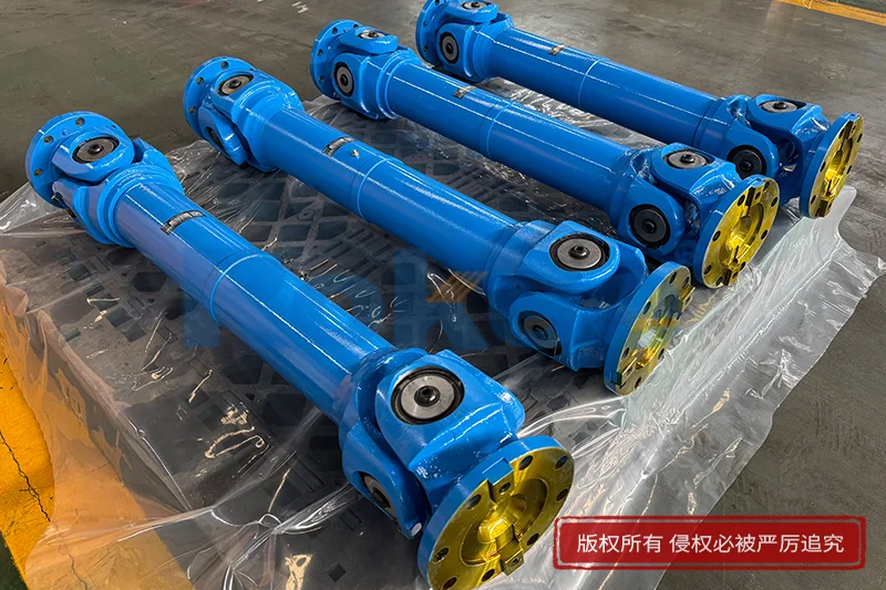
Continuous PU sandwich panel production line represent one of the most demanding and precision-sensitive manufacturing systems in the modern building envelope industry. Unlike batch press machines that cure panels in isolated moulds, a continuous line runs a composite web—typically a pre-coated metal skin, a continuously injected polyurethane core, and a second skin—through a long heated oven tunnel at a steady linear speed, with every station affecting the final dimensional accuracy, surface finish, bond strength, and edge consistency of the panel. Among the many mechanical subsystems that keep this delicate web moving at the correct speed, tension, and alignment, the universal shaft (also known as the universal coupling drive shaft or cardan shaft) that transmits torque between the main gearbox and the line's driven rollers stands out as a silent but decisive factor in overall operation quality. When this transmission element runs smoothly—meaning it transmits rotational energy without pulsation, backlash, angular vibration, or temperature-induced drift—the entire line stabilises, waste drops, and the operator can focus on product quality rather than constantly chasing defects. This article examines how universal shaft transmission quality influences every stage of a continuous PU sandwich panel line, from skin decoiling and laminating through foaming, curing, cutting, and exit stacking, and why engineering for smooth universal-shaft operation has become one of the highest-return improvements a panel plant can make.
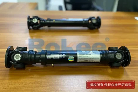
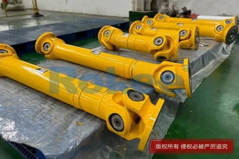
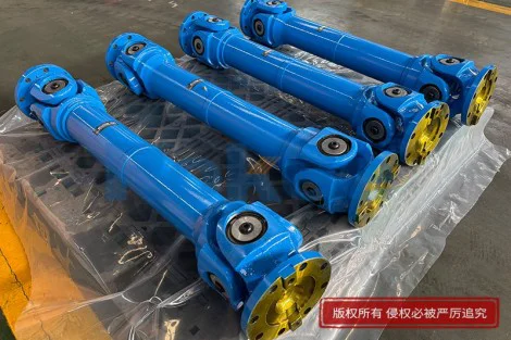
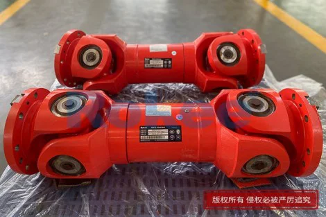
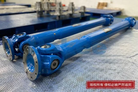
To understand why the universal shaft matters so much, it helps to picture the mechanical layout of a typical continuous line. At the heart of the drive train sits a main motor, usually a variable-frequency or servo-controlled unit, coupled to a reduction gearbox whose output flange connects through one or more universal shafts to the driven rollers of the laminator, the oven conveyor chains, and in some designs the cut-to-length saw and exit conveyor. The universal shaft is the link that crosses the unavoidable misalignment between the gearbox output and the driven shaft—whether that misalignment is angular, parallel, axial, or a combination of the three. In an ideal world the shafts would be perfectly collinear, but in real industrial installations the gearbox sits on a heavy concrete foundation while the rollers are mounted on a steel frame that moves slightly under thermal expansion, that flexes under line tension, and that settles over years of operation. A rigid coupling would either bind, fatigue-crack, or impose destructive radial loads on the bearings. The universal shaft, by contrast, accommodates these offsets through cross-bearing or needle-roller joints at each end while continuing to transmit torque. The trade-off, however, is that a poorly designed or worn universal shaft reintroduces that misalignment into the rotational motion itself, producing torque pulsations, speed ripples, and reactive moments that travel backward into the gearbox and forward into the product web.
The first place where transmission ripple becomes visible is at the entry end of the line, during skin feeding and laminating. PU sandwich panels rely on two facing skins—often pre-painted galvanised steel, aluminium, or sometimes stainless—being fed from coils, passed through a chemical cleaning and priming station, and then brought together in the laminator nip exactly at the moment the PU mixture is injected between them. The speed of each skin must match the line speed within a very tight tolerance; even a small periodic acceleration or deceleration caused by universal-shhaft speed ripple creates a transient in skin tension. Because the skins are thin and highly elastic in tension, those transients appear immediately as longitudinal waviness, as "gauge bands" where the skin stretches slightly thinner over a short length, or as micro-slip between the skin and the PU core once foaming begins. A smooth universal shaft, running with properly phased double-joint geometry and fresh lubricated cross bearings, delivers near-constant angular velocity across its working angle. This steadiness lets the line maintain a constant skin tension that the operator can set once and leave, rather than micro-adjusting the tensioner every few minutes to chase wavy panels. The result at the entry is a flatter skin, a more uniform injection window, and fewer early scrap panels at coil changeovers.
Moving downstream, the foaming station is where universal-shaft smoothness exerts its most profound influence on product quality. On a continuous line, PU is injected between the two skins by a traversing mixing head that moves side to side across the web, laying down a serpentine bead of reacting chemical mixture. The mixture rises, expands in volume by roughly thirty to forty times, and fills the cavity between the skins while the web travels through the oven at line speed. The crucial point is that the expansion chemistry is time-dependent: the cream time, rise time, and gel time are fixed by the formulation, not by the machine. If the web speed fluctuates—even by a few percent in a periodic way—then the residence time of each incremental slice of panel inside the oven fluctuates as well. A universal shaft that introduces torsional ripple, for example because of worn cross bearings, backlash in the spline, or an incorrect working angle that violates the constant-velocity phasing, will cause the driven rollers to accelerate and decelerate in rhythm with each shaft revolution. The panel web speeds up and slows down with it. The chemical reaction, however, does not accelerate and decelerate. The outcome is a panel whose core density varies along its length—denser where the web was moving slower (more chemical per unit length), lighter where it was moving faster—and whose curing state at the exit is uneven. These density bands, invisible at first, show up later as flatness defects, as variations in thermal conductivity, and as inconsistent mechanical strength along the panel span. A smooth universal shaft erases this periodic speed variation, giving the foaming chemistry a steady conveyor to ride on and producing a panel whose core density is uniform from the first cut to the last.
The oven section itself amplifies the importance of steady motion. Continuous PU oven tunnels are long—often thirty to sixty metres of heated zones where temperature is carefully profiled from a high initial rise through a soak period to a controlled cool-down. The web moves through these zones on a conveyor, typically a double-band or chain-guided system whose driven rollers are connected through universal shafts to the main drive train. If the universal shaft transmits pulsating torque, the conveyor does not advance smoothly but rather micro-stutters—an imperceptible jerk per revolution, repeated many times per minute. Over a sixty-metre oven, these micro-stutters accumulate. The reacting PU core, which is in a soft, gel-like state during much of its journey, is particularly sensitive to shear and acceleration disturbances. A steady conveyor lets the rising foam expand vertically against the upper band in an orderly way, producing a flat panel. A stuttering conveyor, by contrast, imparts small longitudinal shear forces into the still-soft core. Those shear forces can create internal voids near the skin interface, can tilt the rising foam cells slightly off vertical, and can leave subtle "flow lines" in the cured core that reduce the panel's bending strength and thermal insulation performance. Smooth universal-shaft transmission, by eliminating these micro-stutters, lets the foam rise undisturbed. The panel exits the oven with a flatter skin, a more isotropic cellular core, and a more consistent bond between skin and core—all outcomes that are difficult to achieve purely through chemical formulation but easy to maintain once the mechanical drive is quiet.
The cut-to-length station is another critical area. Modern continuous lines use a flying saw or a guillotine cutter that must synchronise its motion with the moving web, sever the cured panel to a precise length, and return to its starting position—all while the line keeps running. The synchronisation depends on a high-precision encoder reading the actual line speed. If the upstream universal shaft introduces speed ripple, the encoder reads that ripple as if it were real line-speed variation, and the saw's control system chases it. The result can be panels that cut slightly long or short in a periodic pattern, or whose cut edge is not perfectly perpendicular to the panel length. Over a long shift these small length variations accumulate into a measurable length-error band, which causes problems at the construction site where panels must line up along wall and roof seams. A smooth universal shaft upstream means the encoder signal is clean, the flying saw locks onto a steady speed, and the cut length is consistent batch after batch. The downstream exit conveyor, which stacks the freshly cut panels, also benefits: a steady drive prevents the stack from shifting or misaligning as panels are fed in, reducing hand-straightening and the risk of edge damage.
Beyond these product-quality effects, smooth universal-shaft transmission has a measurable impact on the mechanical health of the line itself. A universal shaft running at an excessive working angle, with unlubricated cross bearings, or with backlash in its sliding spline, imposes cyclic radial and bending loads on the connected components. Those loads accelerate wear in the gearbox output bearings, in the driven-roller bearings, in the nip roll bearings, and even in the foundation bolts. Vibration travels through the frame and can loosen fasteners over time. A worn universal shaft also runs hotter—cross bearings with dry or degraded grease can reach temperatures that break down the lubricant further, creating a self-reinforcing cycle of wear. By contrast, a properly specified, well-maintained universal shaft, operating within its recommended angular range, with correctly phased joints, with fresh grease, and with splines that slide freely to accommodate axial movement, runs cool and quiet. The vibration spectrum measured at the gearbox and at the roller bearings drops noticeably. Bearing life extends, gearbox oil remains clean and cool for longer, and the plant experiences fewer unplanned stoppages for bearing replacement or gearbox repair. In a continuous line, every hour of unplanned downtime is disproportionately expensive because the line must be emptied, cleaned, and restarted with a certain amount of scrap at the head of the new run. The preventive value of a smooth universal shaft is therefore not just felt in product quality but in the plant's overall uptime and maintenance budget.
Energy efficiency and noise are two more benefits that plants often discover only after they upgrade their universal shaft arrangement. A universal shaft with binding splines, worn cross bearings, or poor joint phasing does not just transmit torque—it wastes a portion of it as friction heat and as vibration energy that eventually dissipates into the surrounding structure and the factory air. Because a continuous line runs for many hours per day, seven days a week, even a small increase in transmission efficiency compounds into meaningful electricity savings over a year. Smooth rolling-element universal joints, properly lubricated, reduce the parasitic drag at each end of the shaft. The motor draws less current for the same line speed. The temperature of the shaft and its nearby bearings stays within design limits, avoiding thermal expansion that would otherwise introduce new misalignment. Noise is likewise reduced: a worn universal shaft at high speed produces a characteristic rhythmic whine or rattle that travels through the drive train and into the production hall. This noise is not just an occupational nuisance; it is an audible diagnostic of poor transmission. Plants that measure workplace noise often find that upgrading the universal shaft system—shifting to needle-roller cross bearings, improving alignment, and selecting the correct shaft length to keep working angles low—drops the noise level in the drive area by several decibels. A quieter line is also a smoother line, and the two observations are mechanistically linked.
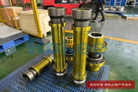
The practical engineering steps that achieve this smoothness are worth summarising, because they are accessible to most existing plants without a full line rebuild. First, ensure the working angle of the universal shaft at each end stays within the manufacturer's recommended range—typically a modest value for continuous-duty service. When the gearbox and driven shaft are offset by more than the recommended angle, the joint reintroduces speed ripple even if it is mechanically sound. Redesigning the shaft length or repositioning the mounting brackets to bring the angle back into range often produces an immediate improvement. Second, use a double-joint (constant-velocity) arrangement where the two joints at each end are phased so that the angular pulsation of one cancels the angular pulsation of the other. This phasing must be correct at installation; a shaft assembled with the yokes out of phase will transmit vibration despite looking symmetric. Third, maintain a disciplined lubrication schedule. Universal shaft cross bearings and splines depend on fresh grease; regreasing at the recommended interval, using the correct grease type, and replacing the shaft when the cross bearings develop measurable play prevents the wear cycle from starting. Fourth, align the line properly during installation and recheck alignment after major maintenance, after foundation settlement, and after frame modifications. Thermal expansion is often underestimated: a steel oven frame can grow tens of millimetres along its length over its operating temperature range, and the universal shaft must be sized and mounted so that this growth is absorbed by the spline, not by binding at the joints. Fifth, consider upgrading to modern universal-shaft designs that integrate needle-roller bearings, enclosed splines, and monitoring features such as temperature or vibration sensors at the bearing caps. These features let maintenance crews detect degradation before it causes a quality issue or a breakdown.
When these steps are taken together, the effect on line operation is transformative. Operators report that the line "feels different"—it runs more quietly, the tension holds steady, the panels come out flatter, the cut length is more consistent, and the daily scrap rate drops. The chemical formulation can be tuned with more confidence because the mechanical noise floor no longer masks the small variations in reaction behaviour. Maintenance crews spend less time chasing bearing failures, less time adjusting tensioners, and less time replacing damaged rollers. The quality department sees fewer customer complaints about flatness, density variation, and dimensional tolerance. Even the plant's energy meter reflects the improvement. Importantly, none of these outcomes depends on a particular product brand, a specific standard grade, or a specific price point; they are the result of good mechanical engineering applied to a transmission element that is often chosen too quickly and then left to run until it fails. In a continuous PU sandwich panel line, where the product is formed by a chemistry that cannot be interrupted or restarted easily, every small mechanical disturbance has a multiplied effect on the final panel. The universal shaft is one of the largest sources of those disturbances when it is neglected, and one of the most reliable sources of stability when it is designed, installed, and maintained for smooth transmission. Investing in that smoothness—through correct geometry, proper phasing, regular lubrication, and disciplined alignment—is therefore not a luxury but a foundational practice that improves operation quality across the entire line, from the coil at entry to the stacked panel bundles at exit. It is a reminder that in high-speed continuous manufacturing, the quietest components often exert the loudest influence on the quality of what the plant ships.